A scripted scatter model offers the flexibility to create a user-defined scatter model based upon an analytical expression. The user can defined a BSDF in terms of any expression containing specular and scatter angles. The scripted scatter model can also be used to vary the scattered ray wavelength and can apply on both transmission and reflection if the Raytrace Controls allow it.
This feature can be accessed by selecting Scripted (BSDF given by user script -- can also modify wavelength) as the Scatter Type in the Create a new scatter model dialog box.
All directional parameters passed by FRED to the script are in direction cosine space and the parameter g_w is the wavelength of an individual scattered ray as both an input and output value.
Values entering the scripted scatter routine are g_Xinc, g_Yinc, g_Zinc (incident ray direction vector components), g_Xspec, g_Yspec, g_Zspec (specular ray direction vector components), g_Xscat, g_Yscat, g_Zscat (scattered ray direction vector components), g_ran (uniformly distributed random number), g_TISrequest (control parameter), g_Xpos, g_Ypos, g_Zpos (ray spatial coordinates) and g_w (ray wavelength). Output values exiting the routine are g_bsdf (model BSDF value) and g_frac (spatial TIS scale factor). The incident direction vector (g_Xinc, g_Yinc and g_Zinc) is specified in a "surface normal local" coordinate system local to the ray intersection point having the surface normal as the +Z direction and preserving (as much as possible) the global Y axis.
When the model is constructed, a reference TIS is requested from the model and is computed at the g_Xpos, g_Ypos and g_Zpos values. During this TIS request, the g_frac parameter is used to specify what fraction of the TIS computed at g_Xpos, g_Ypos and g_Zpos should be used to construct the reference TIS table. When the model is not being requested for a reference TIS, g_frac can be defined with some spatial dependence on g_Xpos, g_Ypos and g_Zpos and controls how much power is taken out of the incident ray when generating scatter. Note that the g_frac parameter is independent of the g_bsdf parameter and there is no requirement that they vary spatially in the same way. Consequently, varying g_frac does not affect the computation of g_bsdf unless it is specifically applied. For clarity, it is recommended that the g_Xpos, g_Ypos, and g_Zpos values selected for calculating the reference TIS correspond to the maximum TIS value such that g_frac = 1.
The example below demonstrates a lambertian scatter model which varies spatially in Y according to a |Sin| function. Note that the reference TIS position is selected to be Y=0.5, where the TIS is a maximum and g_frac is 1.0. Although not a requirement of a generic scatter model, the TIS and the BSDF vary in the same manner spatially such that g_frac is used in the calculation of the BSDF.
Sub EvalScatter( ByVal g_Xinc#, ByVal g_Yinc#, ByVal g_Zinc#, ByVal g_Xspec#, ByVal g_Yspec#, ByVal g_Zspec#, ByVal g_Xscat#, ByVal g_Yscat#, ByVal g_Zscat#, ByVal g_ran#, ByVal g_TISrequest As Boolean, ByRef g_Xpos#, ByRef g_Ypos#, ByRef g_Zpos#, ByRef g_w#, ByRef g_frac#, ByRef g_numA&, ByRef g_numB&, ByRef g_bsdf# )
Const refl=0.5 'reflectivity If Not g_TISrequest Then g_frac = Abs( Sin(PI()*g_Ypos) ) g_bsdf = refl*g_frac/PI()
Else g_Xpos = 0 : g_Ypos = 0.5 : g_Zpos = 0 : g_frac = 1 : g_w = 0.5875618 g_numA = 101 : g_numB = 101 End If
End Sub
It is strongly recommended that the script make no modifications to other nodes in the FRED document.
If a change is made to the document during the raytrace by way of the scripted entity, the state of the document as seen by each individual thread of the raytrace will be inconsistently defined and the results of the raytrace may not be valid.
The TIS value is computed at the specified wavelength when g_TISrequest is True. If g_bsdf has no wavelength dependence, then changing the value of g_w in the TIS request process will have no effect.
During the raytrace, scattered rays will acquire the wavelength value g_w as specified in the script when g_TISrequest is False. If the wavelength value is not changed in this portion of the script, the scattered rays will have the same wavelength as the incident ray.
Scatter in transmission and reflection All scatter models describe the BSDF as measured over a maximum of 2p steradians. Both transmitted and reflected scatter can be modeled by specifying the two scatter directions simultaneously with the appropriate direction controls found under the Scatter tab in the Surface Dialog.
Multiple scatter models can be attached to the same surface. The scatter direction controls are then imposed on every attached model.
2D and 3D plots of a scatter model can be created by right-clicking on the model entry in the Scatterer Folder and selecting Plot 2D (Angle), Plot 2D (Beta-Beta0) or Plot 3D.
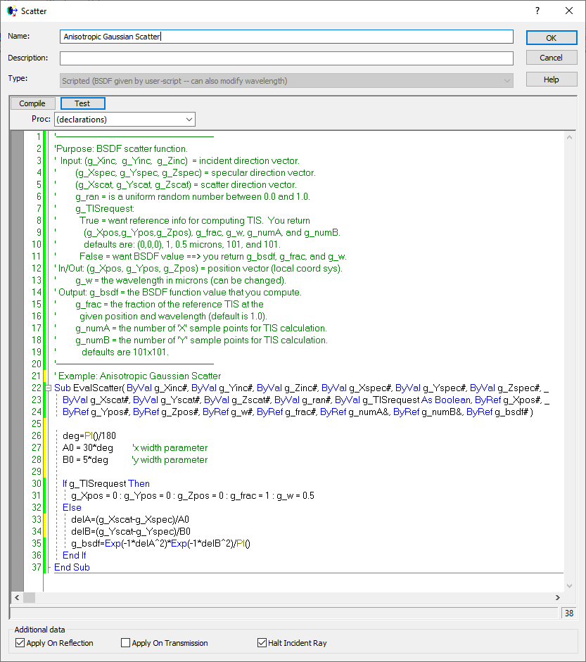
Example - Anisotropic diffuser The following script example illustrates the use of a scripted scatter model to create an anisotropic scatter model for use with a diffuser. This BSDF is defined as a gaussian in direction cosine space. The script definition and intensity distribution are shown below.
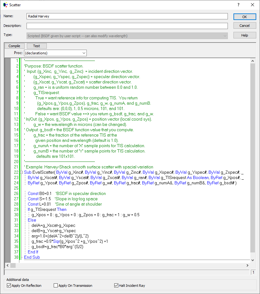
The following script example illustrates the implementation of a spatially varying scatter model using the default scripted scatter model of Harvey. In this example, both the TIS and the BSDF are defined as varying radially with position. Note that in addition to defining g_frac, the BSDF value is also multiplied by this factor.
Shown here is the 5-term Harvey model as a scripted scatter model.
ABg – for polished surface scatter Binomial - plane symmetric case of general Polynomial Extended Harvey-Shack - shift variant form of the Harvey-Shack model Extended Scripted - User-defined scattering function that allows manipulation of the scattered rays' polarization state Flat Black Paint – specify Total Integrated Scatter (TIS) Harvey-Shack – for polished surface scatter K-Correlation – analytic PSD Lambertian – for diffuse scatter Phong – cosn from specular Polynomial - General polynomial with diffuse and Lorentzian component Surface Particle (Mie) – for particulate contamination Tabulated BSDF – measured BSDF data Tabulated PSD – measured PSD data
|
|||||||||||||||||||||||||||||||||||||||||||||||||||
.png)
.png)
.png)
.png)