The Scatterers folder contains the scatter models that may be applied to any surface in FRED. Each model calculates the appropriate three-dimensional Bidirectional Scatter Distribution Function (BSDF) based on the incident ray angles and orientation of the local surface normal. Alternate definitions of the BSDF are the Bidirectional Reflectance Distribution (BRDF) and the Bidirectional Transmission Distribution Function (BTDF).
FRED comes with three default scatter models: Black Lambertian (4% reflectivity diffuse black), White Lambertian (96% reflectivity diffuse white), and Harvey-Shack (polished surface). Additionally, parametric models for the following types of scatterers are also available in FRED: Flat Black Paint (TIS), Extended Harvey-Shack, ABg, Surface Particle (Mie), Phong, Tabulated BSDF, Tabulated PSD, K-Correlation, Binomial and Polynomial. More than one type of scatter model can be applied to a surface. Reflected and transmitted scatter components are allowed or halted per the Raytrace Controls currently applied to the surface.
Every scatter surface must have at least one scatter direction, which can be set automatically, using the menu bar option Tools g Determine Scatter Importance Sampling, or manually, from the Scatter tab in the Surface dialog. Every scatter direction is applied to every scatter model assigned to the surface.
NOTE: Only the coefficients for an existing scatter model can be changed. Once created, the model Type (i.e., Lambertian, TIS, Harvey-Shack, ABg, Mie, Phong) is permanent. A new scatter model must be created and assigned to geometry objects to change the scatter model type.
The Scatterers folder can be found on the left hand side of the FRED document view in the object tree. Mouse clicking the + or - symbol next to the folder on the object tree will expand or collapse the node.
Right mouse clicking the Scatterers folder on the object tree allows selection of the following options:
Summary Report The summary report prints a list of the currently defined scatterers and their descriptions.
Detailed Report The Detailed Report option prints a list of the currently defined scatterers, their descriptions, and their parameter values.
Create a New Scatterer This option allows creation of a new scatter model through which the user can create a scatter model of any type.
BSDF – Bidirectional Scatter Distribution Function = Radiance (L) / Incident Irradiance (E) •Units are inverse Steradians (sr-1) •Defined over a hemisphere = 2p Steradians
BRDF – Bidirectional Reflectance Distribution Function – BSDF for reflected scatter
BTDF – Bidirectional Transmission Distribution Function – BSDF for transmitted scatter
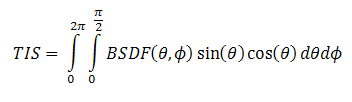
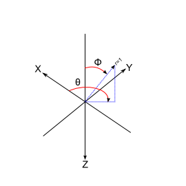
Total Integrated Scatter (TIS) – total scattered power from a surface divided by the incident power, equivalent to an integral of the BSDF carried out over the hemisphere in the coordinate system shown below.
•TIS is related to RMS surface roughness by the following expression
•Dn = change in refractive index change across the surface boundary. Note: Dn = -2n0 for reflected scatter •srms = RMS surface roughness •l = wavelength of incident light •Valid only when srms << l
Projected solid angle (PSA) – projected area of a surface divided by the distance squared •PSA for a hemisphere = p •PSA for a tilted plane = A*cos(q)/d2
Lambertian surface – any surface with equal scatter (brightness) in all directions. •BSDFlambertian = TIS/p
Plane of incidence – the plane containing both the incident and specular rays. The 2-dimensional representation of the BSDF commonly shown in the plane of incidence as a function of b-b0 or log(|b-b0|). •b0 = sine of the angle from the surface normal to the specular ray in the plane of incidence •b = sine of the angle from the surface normal to the scattered ray in the plane of incidence •In the case of forward scatter b > b0 •In the case of reverse or back scatter b < b0
•For hemispherical scatter, the product of the BSDF and the PSA must be less than or equal to one. •The total power contained in the incident beam is equal to the sum of the reflected, transmitted, scattered, and absorbed components:
Coatings and raytrace controls •Coating specifications on a surface apply only to specular rays. •Allowable scatter directions are determined by the Raytrace Controls.
Scatter and Total Internal Reflection When a ray is incident on a surface in a TIR condition, no transmitted scatter rays will be generated (i.e. TIR overrides transmissive scatter). If your application requires this behavior (ex. a roughened lightpipe), please consider the Surface Roughness attribute instead.
Lambertian for diffuse scatter Harvey-Shack for polished surface scatter ABg for polished surface scatter Phong scatter – cosn from specular Flat Black Paint – specify Total Integrated Scatter (TIS) Surface Particle (Mie) – for particulate contamination Tabulated BSDF - measured BSDF Polynomial - General polynomial with diffuse and Lorentzian terms Binomial - plane symmetric form of Polynomial Scripted Scatter - general scatter model (allows ray wavelengths to be changed) Tabulated PSD - for measured power spectral density K-correlation - analytical PSD model Extended Harvey-Shack - shift variant form of the Harvey-Shack model
|
.gif)
.gif)