|
Description
The Ray Fan type Source Primitive facilitates specification of a set of rays that are all propagating in a fixed plane (XZ or YZ) of the source's local coordinate system and is useful for system verification, debugging and generating graphical layout visualizations.
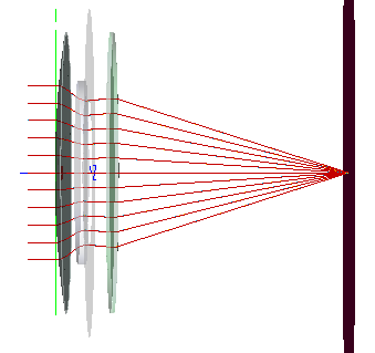
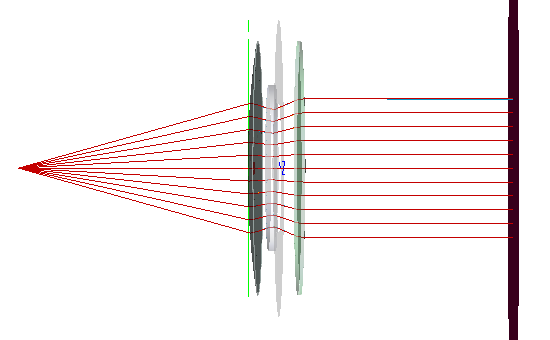
At the source location, a linear aperture is sampled with equally spaced points that define the ray starting positions. Two methods of specifying the ray directions are available; propagation along a direction vector or emission from a specified point. Specifying rays to propagate along a direction vector is useful when the source illumination being represented is a plane wave. Propagation from a specified point is useful when the source illumination being represented is a spherical wave. The figures below show the Y-Z plane of a Triplet lens that is being illuminated by a Ray Fan source in two different configurations. In Figure 1, the source is configured to propagate along the direction vector (0,0,1) and represents plane wave illumination. Consequently, the rays are shown coming to focus at the image plane. In Figure 2, the source is configured to emit from a specified point (0,0,-99.5) and represents a point source. In this particular configuration, the point source lies at the front focal point of the Triplet and the ray fan becomes collimated at the image plane.
|
|
|
Figure 1. Ray fan source aligned to the Y-axis and configured to propagate along the (0,0,1) direction vector. At the source location (far left), the equally spaced rays are propagating in the Y-Z plane.
|
|
|
|
Figure 2. Ray fan source aligned to the Y-axis and configured to propagate from a point located at (0,0,-99.95) with respect to the source location. For each sample point in the source aperture, the ray direction is set such that the ray's trajectory would pass through the specified (x,y,z) point. At the source location (near the first element of the lens), the equally spaced rays are propagating in the Y-Z plane.
|
Navigation
This feature can be accessed in the following ways:
•Menu > Create > Source Primitive > Ray Fan
•Right mouse click on the Optical Sources folder, select Create New Source Primitive > Ray Fan
•Toolbar button: .png)
Controls
|
Control
|
Inputs / Description
|
Defaults
|
|
Logical Parent
|
Read-only. Specifies the source's parent node on the tree.
|
Optical Sources
|
|
Name
|
Name of the source as it will appear on the tree view.
|
Ray Fan N
|
|
Description
|
Description string that will be visible on the tree view.
|
|
|
Parameter Attributes
|
|
0
|
Total power of the source in units of Watts.
|
1.0
|
|
1
|
Specifies the number of evenly spaced ray positions across the diameter of the linear source aperture.
|
11
|
|
2
|
Semi-aperture of the source in document units. The semi-aperture is linear and aligned to the source's local X or Y axis according to parameter 3.
|
0.5
|
|
3
|
Controls the orientation of the ray fan relative to the local source coordinate system. If the "X fan" option is chosen, the rays will propagate in the X-Z plane of the source. If the "Y fan" option is chosen, the rays will propagate in the Y-Z plane of the source.
|
X fan
|
|
4
|
Defines the interpretation of the vector specified in parameter 4.
When the "Along direction" option is used, the vector is interpreted as a direction cosine and all rays will propagate in the specified direction. This mode is useful for specifying the source illumination as a plane wave.
When the "From position" option is used, the vector is interpreted as a position in the coordinate system of the source. The vector between this position and each sample point in the source aperture defines the ray direction at that location in the source aperture. This mode is useful for specifying the source illumination as a point source.
|
Along direction
|
|
5
|
Vector whose interpretation (parameter 4) determines the ray direction at any point within the source aperture. This vector can be entered using the Vector Entry Control interface.
|
0, 0, 1
|
|
6
|
Specifies the Z semi-aperture of the source volume.
|
0.5
|
|
7
|
When toggled, the ray directions are reversed. This has the effect of converting the interpretations of parameter 4 to "From direction" and "Toward position".
Note that when applying this option in combination with "Along direction", the effect is to simply negate the direction vector. If the GUI is closed and re-opened, the direction vector will now show the negated value and the "Reverse rays" option will be untoggled.
|
Unchecked
|
|
Wavelength Attributes
|
|
Single or List
|
In the following descriptions, N is the number of ray positions in the source aperture (parameter 1).
When the Single wavelength option is selected, N rays will be generated at the specified wavelength.
When the List wavelength option is selected, N*M rays will be generated. M is the number of active wavelengths with non-zero weights specified in the wavelength list.
|
Single at the default wavelength
|
|
Source Draw Color
|
If the Single wavelength option is selected, this setting controls the ray position and trajectory draw colors.
If the List wavelength option is selected, this setting only controls the ray position draw color. Ray trajectory draw color is controlled by the color specifications in the wavelength List for each wavelength.
|
|
|
Polarization
|
|
Polarization
|
If checked, polarization data for the rays is maintained and stored.
|
Unchecked
|
|
Handedness
|
Sets the handedness of the polarization state (relevant for non-linear polarization states). If the ray is propagating towards you, the electric field vector rotates in a clockwise direction for Right handedness and counter-clockwise for Left handedness.
Note that for linear polarization, the application of Left or Right handedness is arbitrary. The user may find that the UI display switches handedness depending on the angle of the linear polarization state entered, but this will have no impact on the resulting representation of the linear state.
|
Right
|
|
Ellipticity
|
Sets the ellipticity of the polarization state, 0 represents linear polarization and 1 represents circular.
|
0
|
|
Angle
|
Sets the angle of the polarization relative to the X axis.
|
90
|
|
|
|
OK
|
Accept settings and close dialog box.
|
|
|
Cancel
|
Discard settings and close dialog box.
|
|
|
Apply
|
Accept settings and keep dialog box open.
|
|
|
Help
|
Access this Help page.
|
|
Application Notes
Ray Origination and Visualization
Note that in Figure 2 of the Description section, the ray trajectories are visualized as originating from the specified point location. By default, the rays will originate in the linear aperture at the source primitive location and not at the specified point source location. In order to implement the configuration shown in Figure 2, where the rays originate at the source point location, the following steps should be taken:
1.Create the Ray fan source primitive node with the desired settings and hit Apply or OK to add the node to the object tree
2.Right mouse click on the source primitive node on the tree and select, Edit/View Detailed Optical Source
3.On the Source tab, use the Post-Creation Ray Propagation Specification options in order to propagate the rays from the source primitive plane to the designated point source location (this propagation is free-space and ignores any geometry in the system)
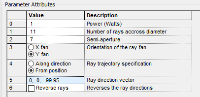
For the source specification in Figure 2, the Source Primitive parameters and Post-Creation Ray Propagation Specification parameters are shown below:
|
|
|
|
Figure 3. Ray fan type Source Primitive parameters corresponding to the visualization shown in Figure 2 of the Description section.
|
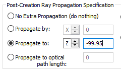
Figure 4. Post-Creation Ray Propagation Specification settings used on the Edit/View Detailed Optical Source controls for the defined Ray fan
|
Related Topics
Plane Wave (incoherent)
Point Source (incoherent)
Lambertian Plane
Lambertian Surface
Rayfile Source
Random Volume into a sphere
Solar Source (simple)
Laser Diode (incoherent)
LED (far-field)
Bitmap
|
Copyright © Photon Engineering, LLC
|
|