|
Description
The Rayfile Source type Source Primitive generates rays using predefined ray data from a file. Ray file data can commonly be downloaded from source vendor websites or may be provided as an output from a source measurement. The following rayfile formats are supported, with preferred formats indicated by an asterisk. Rayfile sizes are limited to 2^31 bytes (~2.15 GB).
|
Rayfile format
|
File extension
|
|
FRED Compact Ray data*
|
FCR
|
|
TM25
|
TM25RAY
|
|
ASCII text
|
DAT
|
|
TracePro binary
|
RAY
|
|
TracePro text
|
DAT
|
|
Zemax binary*
|
DAT
|
|
OPTICAD binary
|
DAT
|
|
LightTools text
|
RAY
|
|
ASAP binary*
|
DIS
|
|
LucidShape binary
|
RAY
|
Rayfile data can be stored with a variety of options concerning power units and spectral content that must be correctly processed and interpreted in order to extract the ray data. Should the user encounter a rayfile that is unsupported or incorrectly processed, please contact FRED technical support so that the rayfile contents can be reviewed.
Upon loading a rayfile into the Rayfile Source, the following actions may occur:
•The total power contained in the rayset will be presented to the user. Power units will be indicated if specified in the ray file.
•The total power in the source is automatically updated to match the total power from the rayfile.
•If the power units in the rayfile are known, the power units in the source specification will be automatically updated. If the power units in the rayfile are unspecified, then the power units of the source specification will be unchanged.
•Summary information regarding the rayfile contents (ray count, flux, spectral content, file type, etc.) will be listed in the Description column next to the rayfile Select button.
Verification of the Rayfile Source should be performed by comparing spatial (irradiance, illuminance, color image) and angular (intensity, luminous intensity) analyses and comparing the resulting metrics to those provided by the vendor or measurement service. As an example, a model of a Luxeon F Plus Cool White LED is constructed and compared to the properties listed in the LED specification sheet.
|
|
|
|
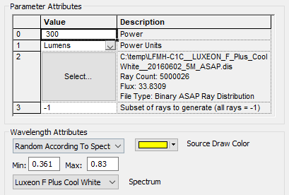
Figure 1. Rayfile Source dialog configured for a Luxeon F Plus with a Cool White spectrum. The provided rayfile contains no spectral data, so a Spectrum node has been created on the FRED tree and applied to the source definition using the "Random according to spectrum" wavelength option. Spectral power distribution of the source is provided by the vendor separately.
|
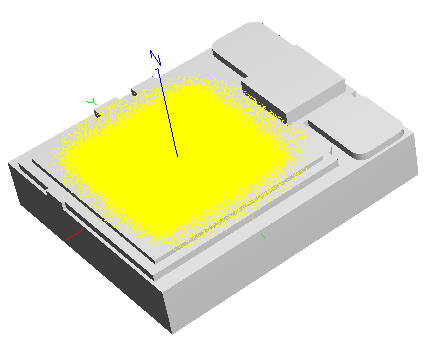
Figure 2. The Rayfile Source as seen in the 3D view after creation. The mechanical model is provided by the LED vendor and imported separately from the rayfile.
|
|
.png)
|
|
|
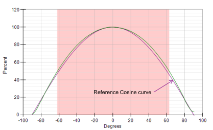
Figure 3. After generating the source rays and calling the Luminous Intensity analysis, the profile slice above shows the simulated intensity distribution in units of Candela. The distribution shown here has been normalized for comparison with the vendor datasheet.
|
Figure 4. Normalized intensity distribution from the vendor datasheet.
|
|
|
|
|
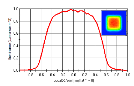
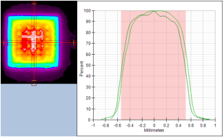
Figure 5. After generating the source rays and calling the Illuminance analysis, a profile slice through the distribution (inset) is shown with units of Lumens/mm2. The distribution is normalized for comparison with the vendor datasheet.
|
Figure 6. Normalized Luminance distribution from the vendor datasheet.
|
|
|
Source Property
|
From vendor datasheet
|
FRED verification
|
|
Luminous flux
|
268 - 330 lumens, minimum
|
300 lumens, reported in the output window by the Luminous Intensity and Illuminance analyses
|
|
Color Temperature
|
~5850K, CIE1931 chromaticity coordinates (0.325,0.335)
|
5650K, CIE 1931 (0.33, 0.35), determined from a Color Image analysis
|
|
Viewing Angle
|
120 degrees (FWHM)
|
124 degrees, determined from Luminous Intensity profile plots
|
|
Navigation
This feature can be accessed in the following ways:
•Menu > Create > Source Primitive > Rayfile Source
•Right mouse click on the Optical Sources folder, select Create New Source Primitive > Rayfile Source
•Toolbar button:.png)
Controls
|
Control
|
Inputs / Description
|
Defaults
|
|
Logical Parent
|
Read-only. Specifies the source's parent node on the tree.
|
Optical Sources
|
|
Name
|
Name of the source as it will appear on the tree view.
|
Rayfile Source N
|
|
Description
|
Description string that will be visible on the tree view.
|
|
|
Parameter Attributes
|
|
0
|
Total power of the source. After the rayfile is loaded, this value may be automatically updated based on the contents of the rayfile. The user can re-enter the desired power after the rayfile is processed.
|
1.0
|
|
1
|
Physical units of the source power, specified as either Watts or Lumens. If the power units in the rayfile are known, the source power units will be automatically updated when the rayfile is processed. When Lumens are used, the source wavelength attributes is forced to use the Random according to spectrum option.
|
Watts
|
|
2
|
Allows selection of the rayfile to be used. When the rayfile is processed, a summary of the rayfile data will be reported in the Description column.
|
|
|
3
|
Allows a random subset of N rays to raytraced. When N = -1, all rays in the rayfile will be traced.
|
|
|
Wavelength Attributes
|
|
Rayfile or Random according to spectrum
|
If the rayfile contains spectral data, the Rayfile wavelength option will generate the rays using the spectral data. If the rayfile does not contain spectral data, then this option cannot be used. A rayfile containing spectral data will be the most accurate way to preserve the source's chromatic spatial and angular characteristics.
When the Random according to spectrum option is selected, each ray will be generated with a unique wavelength whose value is selected by using the designated spectrum as a probability distribution. The spectrum to be used needs to exist in the Spectra folder before it can be applied to a Rayfile Source.
|
Rayfile
|
|
Source Draw Color
|
This setting controls the ray position and trajectory draw colors.
|
|
|
Polarization
|
|
Polarization
|
If checked, polarization data for the rays is maintained and stored.
|
Unchecked
|
|
Handedness
|
Sets the handedness of the polarization state (relevant for non-linear polarization states). If the ray is propagating towards you, the electric field vector rotates in a clockwise direction for Right handedness and counter-clockwise for Left handedness.
Note that for linear polarization, the application of Left or Right handedness is arbitrary. The user may find that the UI display switches handedness depending on the angle of the linear polarization state entered, but this will have no impact on the resulting representation of the linear state.
|
Right
|
|
Ellipticity
|
Sets the ellipticity of the polarization state, 0 represents linear polarization and 1 represents circular.
|
0
|
|
Angle
|
Sets the angle of the polarization relative to the X axis.
|
90
|
|
|
|
OK
|
Accept settings and close dialog box.
|
|
|
Cancel
|
Discard settings and close dialog box.
|
|
|
Apply
|
Accept settings and keep dialog box open.
|
|
|
Help
|
Access this Help page.
|
|
Related Topics
Plane Wave (incoherent)
Point Source (incoherent)
Lambertian Plane
Lambertian Surface
Random Volume into a sphere
Ray Fan
Solar Source (simple)
Laser Diode (incoherent)
LED (far-field)
Bitmap
|
Copyright © Photon Engineering, LLC
|
|