|
Description
The Laser Diode (incoherent) type Source Primitive can be used to build an approximate representation of an astigmatic Gaussian beam using incoherent, geometric rays. The spatial and angular beam profiles in the X and Y axes of the source can be asymmetric and have independently controlled Gaussian exponents. Coherent field propagation effects, such as diffraction, are not captured by this source representation.
The spatial and angular profiles of the source emission are given by the following functions:
|
Spatial Distribution
|
Angular Distribution
|
|
.png)
|
.png)
|
|
x, y
|
Position in the source aperture
|
Qx, Qy
|
Angular direction
|
|
wx, wy
|
1/e2 beam radius
|
ax, ay
|
1/e2 beam semi-angle
|
|
Gx, Gy
|
Super-Gaussian exponents
|
Hx, Hy
|
Super-Gaussian exponents
|
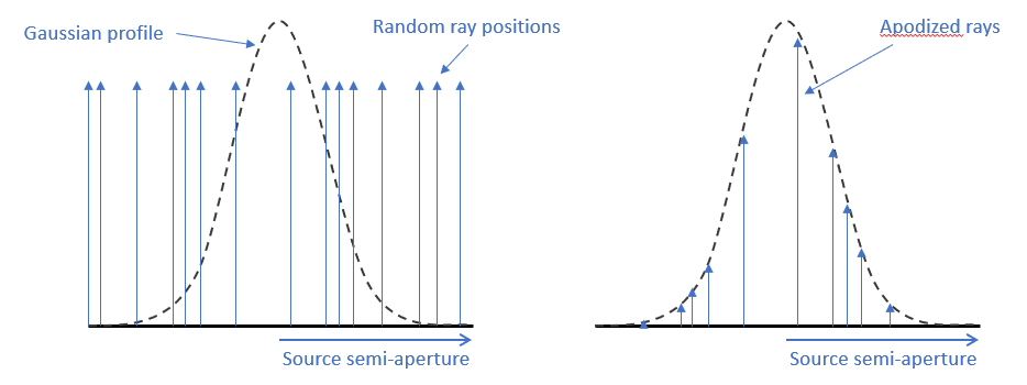
Construction of the source's spatial and directional power profiles is implemented through the use of spatial and directional apodization functions. A graphical representation of the apodization approach is shown in the figure below for spatial sampling of a beam profile, but the same approach applies for directional apodization. In the left side of the image, the black line at the bottom represents the source aperture and random sample points are selected from within this aperture. The Gaussian spatial profile to be applied is represented by the dashed line. When the rays are generated, the flux of each ray is weighted (apodized) according to the function of the spatial profile such that the total flux from all rays also recovers the requested total power of the source.
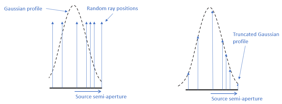
In this model, the user needs to define both the beam properties (1/e2 widths, 1/e2 divergence angles, Gaussian exponents) and the ray sampling properties (source semi-apertures, maximum sampling angles, spatial and directional sampling counts). Independent control of these parameters allows for tuning of the ray sampling for best raytrace efficiency in a given application. It does, however, mean that the user needs to be aware of the scenario below, where the spatial semi-aperture of the source does not extend into the low amplitude region (the tail) of the Gaussian distribution. The result of this is that the apodized rays really represent a truncated Gaussian distribution, since the low amplitude tails of the distribution were never sampled by rays. The same behavior applies to the directional apodization.
When the source semi-aperture becomes significantly larger than the beam width, then many rays are sampling the low-amplitude regions of the apodization function. These rays, while valid, will make relatively insignificant contributions to an overall distribution but cost the same amount of computation time to raytrace as rays with significant flux. Consequently, there is a trade between the area of the source aperture (or angular divergence) relative to the beam properties and the required ray sampling density and calculation time.
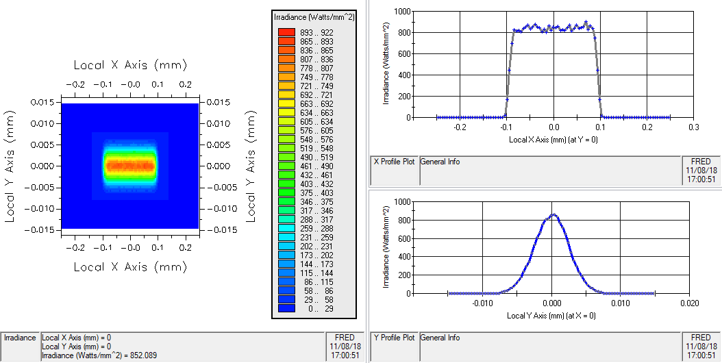
The image below shows the irradiance distribution (power/area) at the source aperture of a Laser Diode (incoherent) type Source Primitive with the spatial parameters given in the following table.
|
Parameter
|
Value
|
|
Number of random ray positions
|
10,000,000
|
|
1/e2 beam radius in X
|
0.1 (mm)
|
|
X semi-aperture of the source plane
|
0.15
|
|
Spatial super-gaussian exponent in X
|
10.0
|
|
1/e2 beam radius in Y
|
0.005
|
|
Y semi-aperture of the source plane
|
0.0075
|
|
Spatial super-gaussian exponent in Y
|
1.0
|
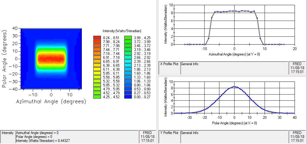
Similarly, the image below shows the intensity distribution (power/steradian) at the source aperture of a Laser Diode (incoherent) type Source Primitive with the directional parameters given in the following table.
|
Parameter
|
Value
|
|
Number of random directions per ray position
|
10,000,000
|
|
1/e2 beam semi-angle in X (deg)
|
8.5
|
|
Source emission semi-angle in X
|
17
|
|
Angular super-gaussian exponent in X
|
10.0
|
|
1/e2 beam semi-angle in Y (deg)
|
20
|
|
Source emission semi-angle in Y
|
40
|
|
Angular super-gaussian exponent in Y
|
1.0
|
The definition of this source is derived from the paper: Nicola Coluccelli, "Nonsequential modeling of laser diode stacks using Zemax: simulation, optimization, and experimental validation," Appl. Opt. 49, 4237-4245 (2010).
Navigation
This feature can be accessed in the following ways:
•Menu > Create > Source Primitive > Laser Diode (incoherent)
•Right mouse click on the Optical Sources folder, select Create New Source Primitive > Laser Diode (incoherent)
•Toolbar button: .png)
Controls
|
Control
|
Inputs / Description
|
Defaults
|
|
Logical Parent
|
Read-only. Specifies the source's parent node on the tree.
|
Optical Sources
|
|
Name
|
Name of the source as it will appear on the tree view.
|
Laser Diode (incoherent) N
|
|
Description
|
Description string that will be visible on the tree view.
|
|
|
Parameter Attributes
|
|
0
|
Total power of the source in units of Watts.
|
1.0
|
|
1
|
Specifies the number of random positions within the source aperture (parameters 4 and 7) at which rays will be generated. The spatial profile of the beam is sampled at these random positions.
|
100
|
|
2
|
Specifies the number of rays emitted from each position (parameter 1). The emitted rays will have randomly selected directions falling within the rectangular angle cone defined by parameters 10 and 13.
|
1
|
|
3
|
Specifies the 1/e2 beam radius along X in document units.
|
0.057
|
|
4
|
Specifies the maximum semi-aperture of the source in the X axis in document units. The beam being represented will only be sampled out to this distance along the X axis.
|
0.114
|
|
5
|
Specifies the spatial super-Gaussian exponent in the X axis.
|
10.0
|
|
6
|
Specifies the 1/e2 beam radius along Y in document units.
|
0.0005
|
|
7
|
Specifies the maximum semi-aperture of the source in the Y axis in document units. The beam being represented will only be sampled out to this distance along the Y axis.
|
0.001
|
|
8
|
Specifies the spatial super-Gaussian exponent in the Y axis.
|
1.0
|
|
9
|
Specifies the 1/e2 beam divergence semi-angle along the X-axis. Units are degrees.
|
8.5
|
|
10
|
Specifies the maximum ray emission semi-angle along the X axis. The beam being represented will only be sampled out to this angle in X.
|
17
|
|
11
|
Specifies the angular super-Gaussian exponent in the X direction.
|
10
|
|
12
|
Specifies the 1/e2 beam divergence semi-angle along the Y-axis. Units are degrees.
|
34
|
|
13
|
Specifies the maximum ray emission semi-angle along the Y axis. The beam being represented will only be sampled out to this angle in Y.
|
68
|
|
14
|
Specifies the angular super-Gaussian exponent in the Y direction.
|
15
|
|
Wavelength Attributes
|
|
Single
|
With N being the number of ray positions in the source aperture (parameter 1) and M being the number of ray directions emitting from each point (parameter 2), N*M total random rays will be generated at the specified wavelength.
|
Single
|
|
Source Draw Color
|
This setting controls the ray position and trajectory draw colors.
|
|
|
Polarization
|
|
Polarization
|
If checked, polarization data for the rays is maintained and stored.
|
Unchecked
|
|
Handedness
|
Sets the handedness of the polarization state (relevant for non-linear polarization states). If the ray is propagating towards you, the electric field vector rotates in a clockwise direction for Right handedness and counter-clockwise for Left handedness.
Note that for linear polarization, the application of Left or Right handedness is arbitrary. The user may find that the UI display switches handedness depending on the angle of the linear polarization state entered, but this will have no impact on the resulting representation of the linear state.
|
Right
|
|
Ellipticity
|
Sets the ellipticity of the polarization state, 0 represents linear polarization and 1 represents circular.
|
0
|
|
Angle
|
Sets the angle of the polarization relative to the X axis.
|
90
|
|
|
|
OK
|
Accept settings and close dialog box.
|
|
|
Cancel
|
Discard settings and close dialog box.
|
|
|
Apply
|
Accept settings and keep dialog box open.
|
|
|
Help
|
Access this Help page.
|
|
Related Topics
Plane Wave (incoherent)
Point Source (incoherent)
Lambertian Plane
Lambertian Surface
Rayfile Source
Random Volume into a sphere
Ray Fan
Solar Source (simple)
LED (far-field)
Bitmap
|
Copyright © Photon Engineering, LLC
|
|