|
Description
The Vector Entry Control interface is used through out FRED in control specifications requiring x,y,z position triplet or x,y,z direction triplets. Flexible delimiting of the triplet values allows the user to quickly copy and paste entries from a variety of sources directly into the Vector Entry Control interface in order to help facilitate rapid model development and manipulation. Triplet values can be delimited using any combination of the following characters:
|
Recognized Vector Entry Control Delimiters
|
|
,
|
;
|
(
|
|
)
|
<
|
>
|
|
return
|
space
|
tab
|
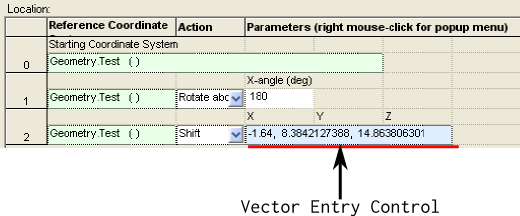
The Vector Entry Control interface will appear with a light blue background where available. For example, the image below shows a portion of the Position/Orientation dialog with the entry in row 2 being a "Shift" type operation that accepts an x,y,z triplet. This "Shift" entry in the Position/Orientation dialog uses the Vector Entry Control interface to specify the position triplet.
Controls
As mentioned above, the Vector Entry Control interface supports the specification of both x,y,z position triplets and x,y,z direction triplets. Depending on which type is being specified (position or direction) the functionality of the interface will change.
Specification of Position Triplets
There are two ways to specify an x,y,z position triplet in the Vector Entry Control interface:
1. Direct entry of delimited values into the control interface (either hand entry or copy/paste from another source).
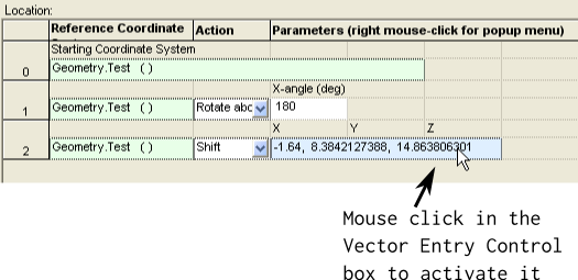
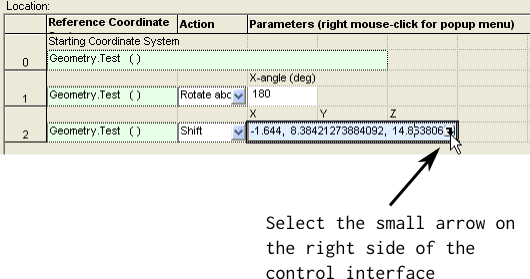
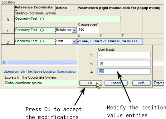
2. Activation of the Vector Entry Control interface and value entry.
The second option, activation of the control interface and value entry, can be performed in the following way:
Specification of Direction Triplets
There are two ways to specify an x,y,z direction triplet in the Vector Entry Control interface:
1. Direct entry of delimited values into the control interface (either hand entry or copy/paste from another source).
2. Activation of the Vector Entry Control interface and value entry.
When using option 1 above, the values entered simply represent the direction components along the x, y and z axes. Specifying the direction triplet using Option 2 above proceeds in the same manner as that described for the position entry control, though the interface provides many more options for entering the direction values. Below is an image of the Vector Entry Control interface for direction triplets:
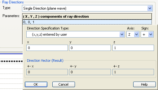
The various components in the Vector Entry Control interface for direction specifications have the following behavior:
|
Component
|
Behavior
|
|
Direction Specification Type
|
Designates how the x,y,z entries input by the user are to be interpreted.
|
|
Axis
|
Designates the component of the direction vector result which is solved for. See the specific specification type descriptions below.
|
|
Sign
|
Designates whether the component direction vector results are negated in sign or left unmodified.
|
|
x,y,z
|
User-input fields. See the specific specification type descriptions below.
|
|
Direction Vector (Result)
|
Resultant x,y,z component direction vector which will be returned to the dialog that called the vector entry control interface.
|
|
Specification Type
|
Application
|
|
(x,y,z) entered by user
|
Specifies the direction components along the x,y,z axes directly. The Axis option does not apply, but the Sign option will apply a negative when the "-" option is selected.
|
|
S - two components (A,B), compute third for unit length
|
User specifies 2 of the three components along the x,y,z axes and the third component is solved for so that the vector is unit length. The solved component is specified by the Axis parameter. The Sign parameter specifies whether the solved component is positive or negative. This is equivalent to the C type specification.
|
|
SD - sines of two angles (a,b) in degrees, compute for unit length
|
Two angles, a and b, are entered in degrees. The Sines of the values are taken as the corresponding axis components and the component specified by the Axis parameter is solved for. The Sign parameter specifies whether the solved component is positive or negative.
|
|
SR - sines of two angles (a,b) in radians, compute for unit length
|
Two angles, a and b, are entered in radians. The Sines of the values are taken as the corresponding axis components and the component specified by the Axis parameter is solved for. The Sign parameter specifies whether the solved component is positive or negative.
|
|
C - two components (A,B), compute third for unit length
|
User specifies 2 of the three components along the x,y,z axes and the third component is solved for so that the vector is unit length. The solved component is specified by the Axis parameter. The Sign parameter specifies whether the solved component is positive or negative. This is equivalent to the S type specification.
|
|
CD - cosines of two angles (a,b) in degrees, compute for unit length
|
Two angles, a and b, are entered in degrees. The Cosines of the values are taken as the corresponding axis components and the component specified by the Axis parameter is solved for. The Sign parameter specifies whether the solved component is positive or negative.
|
|
CR - cosines of two angles (a,b) in radians, compute for unit length
|
Two angles, a and b, are entered in radians. The Cosines of the values are taken as the corresponding axis components and the component specified by the Axis parameter is solved for. The Sign parameter specifies whether the solved component is positive or negative.
|
|
T - two components (A,B), third set to 1.0
|
User specifies two components, A and B, and the component specified by the Axis parameter is set to 1. The Sign parameter specifies whether the Axis component is positive or negative.
|
|
TD - tangents of two angles (a,b) in degrees, third set to 1.0
|
Two angles, a and b, are entered in degrees. The Tangents of their values are taken as the corresponding axis components and the component specified by the Axis parameter is set to 1.0. The Sign parameter specifies whether the Axis component is positive or negative.
|
|
TR - tangents of two angles (a,b) in radians, third set to 1.0
|
Two angles, a and b, are entered in radians. The Tangents of their values are taken as the corresponding axis components and the component specified by the Axis parameter is set to 1.0. The Sign parameter specifies whether the Axis component is positive or negative.
|
|
PD - polar and azimuth spherical angles (a,b) in degrees
|
User specifies the polar and azimuth angles in degrees, a and b, for a spherical coordinate system. The Axis parameter specifies the polar angle reference, whose value is then calculated as +- cos(a). The remaining axes must form a right handed coordinate system with the first component value being +-sin(a)cos(b) and the second component value being +-sin(a)sin(b). For example, with the Axes parameter set to Z, the values are computed in the following way:
x = sin(a)cos(b)
y = sin(a)sin(b)
z = cos(a)
The sign parameter determines whether the vector components are all positive or negative.
|
|
PR - polar and azimuth spherical angles (a,b) in radians
|
User specifies the polar and azimuth angles in radians, a and b, for a spherical coordinate system. The Axis parameter specifies the polar angle reference, whose value is then calculated as +- cos(a). The remaining axes must form a right handed coordinate system with the first component value being +-sin(a)cos(b) and the second component value being +-sin(a)sin(b). For example, with the Axes parameter set to Z, the values are computed in the following way:
x = sin(a)cos(b)
y = sin(a)sin(b)
z = cos(a)
The sign parameter determines whether the vector components are all positive or negative.
|
|
QD - latitude and longitude spherical angles (a,b) in degrees
|
User specifies the latitude and longitude angles in degrees, a and b, for a latitude and longitude spherical coordinate system. The Axis parameter specifies the latitude angle reference, whose value is then calculated as +- sin(a). The remaining axes must form a right handed coordinate system with the first component value being +-cos(a)cos(b) and the second component value being +-cos(a)sin(b). For example, with the Axes parameter set to Z, the values are computed in the following way:
x = cos(a)cos(b)
y = cos(a)sin(b)
z = sin(a)
The sign parameter determines whether the vector components are all positive or negative.
|
|
QR - latitude and longitude spherical angles (a,b) in radians
|
User specifies the latitude and longitude angles in radians, a and b, for a latitude and longitude spherical coordinate system. The Axis parameter specifies the latitude angle reference, whose value is then calculated as +- sin(a). The remaining axes must form a right handed coordinate system with the first component value being +-cos(a)cos(b) and the second component value being +-cos(a)sin(b). For example, with the Axes parameter set to Z, the values are computed in the following way:
x = cos(a)cos(b)
y = cos(a)sin(b)
z = sin(a)
The Sign parameter determines whether the vector components are all positive or negative.
|
|
AD - euler angle (degrees) rotations in a,b order
|
When choosing a direction using Euler angles, the classic third Euler angle is redundant since it is a rotation about the current direction vector. For this reason, the Euler angle specification only requires two angles to be entered by the user.
The rotations angles, a and b, are entered in degrees by the user with the Axis parameter specifying the initial rotation axis and the remaining axes forming a right handed coordinate system. The ordering of the rotations is the alpha rotation first followed by the beta rotation. In this construction, with Axis specified to Z, the vector components are computed in the following way:
x = sin(b)
y = sin(a)cos(b)
z = cos(a)cos(b)
The Sign parameter specifies whether all components are positive or negative.
|
|
AR - euler angle (radians) rotations in a,b order
|
When choosing a direction using Euler angles, the classic third Euler angle is redundant since it is a rotation about the current direction vector. For this reason, the Euler angle specification only requires two angles to be entered by the user.
The rotations angles, a and b, are entered in radians by the user with the Axis parameter specifying the initial rotation axis and the remaining axes forming a right handed coordinate system. The ordering of the rotations is the alpha rotation first followed by the beta rotation. In this construction, with Axis specified to Z, the vector components are computed in the following way:
x = sin(b)
y = sin(a)cos(b)
z = cos(a)cos(b)
The Sign parameter specifies whether all components are positive or negative.
|
|
BD - euler angle (degrees) rotations in b,a order
|
When choosing a direction using Euler angles, the classic third Euler angle is redundant since it is a rotation about the current direction vector. For this reason, the Euler angle specification only requires two angles to be entered by the user.
The rotations angles, a and b, are entered in degrees by the user with the Axis parameter specifying the initial rotation axis and the remaining axes forming a right handed coordinate system. The ordering of the rotations is the beta rotation first followed by the alpha rotation. In this construction, with Axis specified to Z, the vector components are computed in the following way:
x = cos(a)sin(b)
y = sin(a)
z = cos(a)cos(b)
The Sign parameter specifies whether all components are positive or negative.
|
|
BR - euler angle (radians) rotations in b,a order
|
When choosing a direction using Euler angles, the classic third Euler angle is redundant since it is a rotation about the current direction vector. For this reason, the Euler angle specification only requires two angles to be entered by the user.
The rotations angles, a and b, are entered in radians by the user with the Axis parameter specifying the initial rotation axis and the remaining axes forming a right handed coordinate system. The ordering of the rotations is the beta rotation first followed by the alpha rotation. In this construction, with Axis specified to Z, the vector components are computed in the following way:
x = cos(a)sin(b)
y = sin(a)
z = cos(a)cos(b)
The Sign parameter specifies whether all components are positive or negative.
|
|
XD - fixed axis angle (degrees) rotations in a,b order
|
The user specifies two rotation angles, a and b, in degrees. The Axis parameter indicates the fixed axis which is not explicitly rotated about. The two angles, a and b, then correspond to the remaining axis that form a right handed coordinate system. For example, if the Axis parameter is set to Z, then there will be no rotation about the Z axis and the components are evaluated in the following way:
x = cos(a)sin(b)
y = sin(a)
z = cos(a)cos(b)
There is first a rotation about the x-axis by angle a and then a rotation about the y-axis by angle b.
The Sign parameter specifies whether the values are negative or positive.
|
|
XR - fixed axis angle (radians) rotations in a,b order
|
The user specifies two rotation angles, a and b, in radians. The Axis parameter indicates the fixed axis which is not explicitly rotated about. The two angles, a and b, then correspond to the remaining axis that form a right handed coordinate system. For example, if the Axis parameter is set to Z, then there will be no rotation about the Z axis and the components are evaluated in the following way:
x = cos(a)sin(b)
y = sin(a)
z = cos(a)cos(b)
There is first a rotation about the x-axis by angle a and then a rotation about the y-axis by angle b.
The Sign parameter specifies whether the values are negative or positive.
|
|
YD - fixed axis angle (degrees) rotations in b,a order
|
The user specifies two rotation angles, a and b, in degrees. The Axis parameter indicates the fixed axis which is not explicitly rotated about. The two angles, a and b, then correspond to the remaining axis that form a right handed coordinate system. For example, if the Axis parameter is set to Z, then there will be no rotation about the Z axis and the components are evaluated in the following way:
x = sin(b)
y = sin(a)cos(b)
z = cos(a)cos(b)
There is first a rotation about the y-axis by angle b and then a rotation about the x-axis by angle a.
The Sign parameter specifies whether the values are negative or positive.
|
|
YR - fixed axis angle (radians) rotations in b,a order
|
The user specifies two rotation angles, a and b, in radians. The Axis parameter indicates the fixed axis which is not explicitly rotated about. The two angles, a and b, then correspond to the remaining axis that form a right handed coordinate system. For example, if the Axis parameter is set to Z, then there will be no rotation about the Z axis and the components are evaluated in the following way:
x = sin(b)
y = sin(a)cos(b)
z = cos(a)cos(b)
There is first a rotation about the y-axis by angle b and then a rotation about the x-axis by angle a.
The Sign parameter specifies whether the values are negative or positive.
|
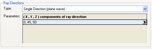
Shorthand Specification of Direction Triplets
As described in the section above, the direction triplet vector entry control interface has a variety of coordinate system options that can be used to specify the direction vector. Note that each coordinate system option is identified by a one or two letter code (ex. YR, XD, S, etc.). If the user already knows the letter code of the coordinate system they wish to use, a shorthand input method can be used so that the user does not need to activate the full vector entry control dialog. The letter code of the coordinate system specification can be input directly into the vector entry control dialog in the position corresponding to the Axis parameter, with the remaining values being entered in the units required by the coordinate system. For example, suppose the user wants to specify a direction in the "SD - sines of two angles (a,b) in degrees, compute for unit length" coordinate system where the vector is 45 degrees from the Z-axis towards the Y-axis and the Axis parameter is set to Z. In shorthand notation, the vector entry for this specification would be shown below:
What does "..., ..., ..." mean?
As seen in the image below, the values of the VEC appear as the string, "..., ..., ...". This indicates that the cell width is too narrow to display the VEC values. In this case, the column width of the GUI dialog needs to be increased. This is accomplished by grabbing the | between the Value and Description columns with your mouse and dragging the column to the appropriate width.
.png)
After increasing the column width:
.png)
Related Topics
Graphical User Interface Summary
Entity Picker
|
Copyright © Photon Engineering, LLC
|
|