|
Description
Detector entities are a type of analysis node which can interact with rays during the raytrace and be defined in a variety of shapes. Ray interaction, as opposed to ray filtering (a post-trace process), allows detector entities the capability to dynamically collect data in any optical space at any time. The detector entities themselves can bin ray data at three separate times, during the raytrace (i.e. using rays that intersect the detector entity at any time during the trace), immediately after the raytrace (i.e. rays that "end" on the detector entity), or on request (i.e. rays "on" the detector entity at the time of request). The results of the ray binning for each detector entity are available to the user in an analysis results node having the same name as the detector entity. Keep in mind that because detector entities are intersected during the raytrace, you should never place a detector entity coincident with other surfaces in the geometry. Failure to obey this rule may result in inconsistent results due to the ambiguity associated with intersecting coincident objects.
The following detector entity shapes and analyses are currently supported:
Detector entities should be used in place of analysis surfaces under the following conditions:
•One of the unique detector entity shapes is required
•Information about the ray distribution in an optical space is desired but not accessible at the end of a raytrace
•Rays are incoherent
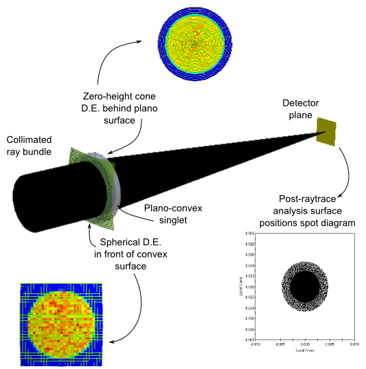
Consider a simple imaging system consisting of a collimated ray bundle incident on a convex-plano singlet being focused down to a detector plane. At the end of the raytrace all rays are associated with the detector plane surface and any information about the power distributions in the other optical spaces of the lens system during the time of the raytrace is lost. Suppose that the spatial distributions of incident power on the convex and plano surfaces of the singlet are of interest. A spherical detector entity can be inserted immediately in front of (but not coincident with) the spherical surface and set to analyze rays traveling from the source into the lens and a planar detector entity (in this example a cone with zero height) can be inserted immediately after the plano surface to analyze rays traveling from the lens to the detector. The following schematic shows the system layout with the resulting irradiance distributions binned by the detector entities during the raytrace (as rays intersected them) as well as the positions spot diagram on the detector calculated after the conclusion of the raytrace using a standard analysis surface.
Navigation
This feature can be accessed in the following ways:
•Menu > Create > New Detector Entity
•On the Analysis Surface(s) folder, right mouse click and select "New Detector Entity" from the list menu
•Use one of the detector entity creation toolbar buttons (      ) )
Controls
Generic Controls
|
Control
|
Inputs / Description
|
Default
|
|
Name
|
Name of the detector entity.
|
Detector Entity n
|
|
Description
|
Description of the detector entity.
|
Depends on Type:
Planar Detector Entity
Cylindrical Detector Entity
Spherical Detector Entity
Cone Detector Entity
3D Box
|
|
Location
|
|
List of position/orientation operations applied to the detector entity.
|
|
Ray Selection (only rays on this entity are considered)
|
|
When the analysis is performed, only rays meeting the ray selection criteria are included in the results. For detector entities, ray selection criteria are applied only to rays that exist on the detector entity. This behavior is different from how ray selection criteria are used in other FRED operations, which are generally applied to any rays in the system regardless of their current entity.
Note: Only incoherent rays are currently included in the detector entity analysis results.
|
|
|
|
OK
|
Accept settings and close dialog.
|
|
|
Cancel
|
Discard settings and close dialog.
|
|
|
Apply
|
Accept settings and keep dialog open.
|
|
|
Help
|
Open the FRED Help
|
|
Common Controls (Resolution, Analysis, Illuminance, Visualization)
|
Control
|
Inputs / Description
|
Default
|
|
Resolution
|
|
ADim
|
A Axis Resolution
Analysis samples along the designated A axis of the detector entity.
|
21
|
|
BDim
|
B Axis Resolution
Analysis samples along the designated B axis of the detector entity.
|
21
|
|
Analysis
|
|
Calculation
|
Analysis type performed on rays passing the detector entity's ray selection criteria. Options are:
•Irradiance
•ColorImageXYZ
•Illuminance
|
Irradiance
|
|
CalcTiming
|
Specifies at when the analysis is performed and when the corresponding analysis results node is created. Options are:
•During Trace: Rays intersecting the detector entity at any point during the trace are binned for analysis. The corresponding analysis results node is created before the start of the raytrace.
•At Trace End: Rays on the detector entity at the end of the raytrace are binned for analysis. Creation of the analysis results node occurs at the conclusion of the raytrace.
•On Request: Rays on the detector entity are binned for analysis when the user selects "Perform Analysis" from the detector entity's context menu. Creation of the analysis results node occurs at this time.
|
At Trace End
|
|
Sidedness
|
Specifies which side of the detector entity rays are collected on. Incoming rays not matching the sidedness specification are excluded from the analysis but still intersect the detector entity. Options are:
•Both Sides
•Positive Side
•Negative Side
The sidedness also determines how many rays are binned in the detector entity analysis. For example, if a single ray is transmit through a spherical detector entity whose sidedness is set to "Both Sides", two rays will be binned on the detector entity. If the spherical detector entity's sidedness is set to either Positive Side or Negative Side, only one ray will be binned in the analysis.
The sidedness specification for each of the detector entity types is the following (images below):
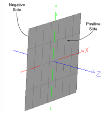
•Plane: The side facing the detector entity's local +Z direction is the positive side and the side facing the local -Z direction is the negative side.
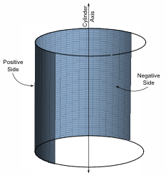
•Cylinder: The side facing towards the cylinder axis is the negative side. The side facing away from the cylinder axis is the positive side.
•Sphere: The side facing towards the sphere center is the negative side. The side facing away from the sphere center is the positive side.
•Cone: The side facing towards the cone axis is the negative side. The side facing away from the cone axis is the positive side.
|
Both Sides
|
|
|
|
|
|
AbsorbRay
|
Rays are stopped on the detector entity upon intersection.
|
True
|
|
Illuminance
|
|
*Only editable if the selected Calculation is Illuminance. Otherwise this section does not apply.
|
|
IllumUnits
|
Units in which the results are reported. Options are:
•Lumens/Area (lm/area)
•LUX (lm/m2)
•Phot (lm/cm2)
•Foot-Candles (lm/ft2)
•Arbitrary Units (specify response spectrum)
|
LUX
|
|
DetRespSpect
|
Detector response spectrum used. Only active when IllumUnits are specified as Arbitrary Units.
|
-None-
|
|
DetRespMult
|
Detector response multiplier. Only active when IllumUnits are specified as Arbitrary Units.
|
1
|
|
Visualization
|
|
Draw
|
Specifies whether the detector entity is drawn in the 3D view.
|
True
|
|
DrawMode
|
Specifies how the detector entity is drawn in the 3D view. Options are:
|
Fill
|
|
DrawColor
|
Specifies the draw color in format (R,G,B), where R, G and B are integers between 0 and 255. Some colors in RGB are:
|
Gray
|
(190,190,190)
|
|
Navy
|
(0,0,128)
|
|
Steel Blue
|
(70,130,180)
|
|
Cyan
|
(0,255,255)
|
|
Dark Green
|
(0,100,0)
|
|
Chartreuse
|
(127,255,0)
|
|
Forest Green
|
(34,139,34)
|
|
Gold
|
(255,215,0)
|
|
Sandy Brown
|
(244,164,96)
|
|
Orange
|
(155,165,0)
|
|
Orange-red
|
(255,69,0)
|
|
Maroon
|
(176,48,96)
|
|
(166,202,240)
|
Plane Specific Controls
|
Control
|
Inputs/Description
|
Default
|
|
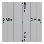
XMin
|
Minimum X range from the center of the detector.
|
-1
|
|
XMax
|
Maximum X range from the center of the detector.
|
1
|
|
YMin
|
Minimum Y range from the center of the detector.
|
-1
|
|
YMax
|
Maximum Y range from the center of the detector
|
1
|
|
|
Cylinder Specific Controls
|
Control
|
Inputs/Description
|
Default
|
|
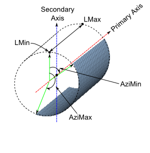
PrimaryAxis
|
The cylinder axis of symmetry.
|
Y
|
|
SecondaryAxis
|
Axis from which azimuthal angles are measured.
|
Z
|
|
AIsPrimary
|
If True, the PrimaryAxis sampling resolution is given by ADim. If False, the PrimaryAxis sampling resolution is given by BDim.
|
False
|
|
Radius
|
Cylinder radius.
|
1
|
|
LMin
|
Start of cylinder as measured from the cylinder's local origin along the PrimaryAxis. Must be less than LMax.
|
-1
|
|
LMax
|
End of cylinder as measured from the cylinder's local origin along the PrimaryAxis.
|
1
|
|
AziMin
|
Minimum azimuthal angle in degrees measured from the SecondaryAxis (-180 and 180). Must be less than AziMax.
|
-180
|
|
AziMax
|
Maximum azimuthal angle in degrees measured from the SecondaryAxis (-180 and 180).
|
180
|
|
|
Sphere Specific Controls
|
Control
|
Inputs/Description
|
Default
|
|
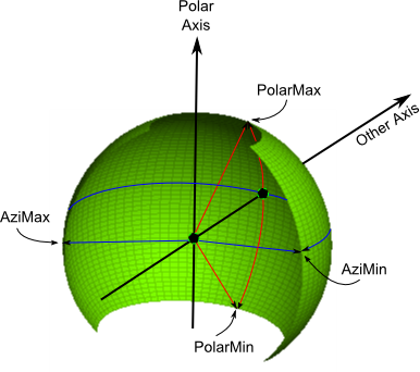
PolarAxis
|
Axis towards which positive polar angles are measured.
|
Y
|
|
OtherAxis
|
Axis from which azimuthal angles are measured. Positive azimuthal angles are determined by the right handed coordinate system formed by the OtherAxis and the PolarAxis.
|
Z
|
|
AIsPolar
|
If True, the PolarAxis sampling resolution is given by ADim. If False, the PolarAxis sampling resolution is given by BDim.
|
False
|
|
Radius
|
Radius of the sphere.
|
1
|
|
PolarMin
|
Minimum polar angle measured in degrees (-90 to 90). Must be less than PolarMax.
|
-90
|
|
PolarMax
|
Maximum polar angle measured in degrees (-90 to 90).
|
90
|
|
AziMin
|
Minimum azimuthal angle measured in degrees from the OtherAxis (-180 to 180). Must be less than AziMax.
|
-180
|
|
AziMax
|
Maximum azimuthal angle measured in degrees from the OtherAxis (-180 to 180).
|
180
|
|
|
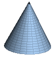
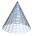
Cone Specific Controls
|
Control
|
Inputs/Description
|
Default
|
|
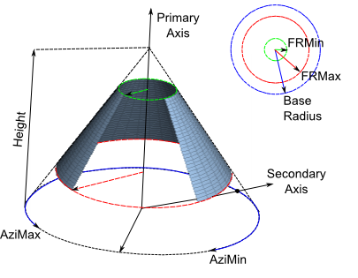
PrimaryAxis
|
Cone axis of symmetry. Height is measured along this axis.
|
Y
|
|
SecondaryAxis
|
Axis from which azimuthal angles are measured. Positive and negative angles are determined by the right handed coordinate system formed by the SecondaryAxis and the PrimaryAxis.
|
Z
|
|
AIsPrimary
|
If true, the PrimaryAxis sampling resolution is given by ADim. If False, the PrimaryAxis sampling resolution is given by BDim.
|
False
|
|
BaseRadius
|
Radius at the cone's base (radus > 0).
|
1
|
|
Height
|
Height of the cone measured along the PrimaryAxis (positive or negative).
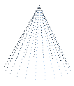
NOTE: if the cone height is zero, this becomes a plane detector with radial symmetry.
|
0.5
|
|
FRMin
|
Minimum radius of the cone as a fraction of the base radius (from 0 to 1 and less than FRMax). The region of the cone bounded by FRMin, FRMax, AziMin and AziMax defines the detector entity.
|
0
|
|
FRMax
|
Maximum radius of the cone as a fraction of the base radius (from 0 to 1 and greater than FRMin). The region of the cone bounded by FRMin, FRMax, AziMin and AziMax defines the detector entity.
|
1
|
|
AziMin
|
Minimum azimuthal angle measured in degrees from the SecondaryAxis (-180 to 180). Must be less than AziMax.
|
-180
|
|
AziMax
|
Maximum azimuthal angle measured in degrees from the SecondaryAxis (-180 to 180).
|
180
|
|
|
|
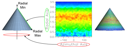
Although this parameter is not explicitly called out in the controls for the Cone type detector entity, there is a Radial Axis to the cone which will be displayed in the corresponding analysis results. The radial axis connects the tip of the cone along the primary axis to the base radius along the secondary axis, as shown in the diagram below.
|
Application Notes
Ray Intersection Count
Intersections with the surface of a detector entity (3D Box type excluded), the intersections are included in the rays' intersection count parameter.
3D View Rendering
A maximum of 1024 columns and 1024 rows will be drawn in the 3D view for a 2D detector entity. Analyses calculations performed by the detector entities are unaffected by this limitation.
Related Topics
3D Box Detector Entity
Analysis Surface
Directional Analysis Entity
|
Copyright © Photon Engineering, LLC
|
|
.png)
.png)