The Position/Orientation feature allows placement of an entity in any coordinate system and with any combination of linear transformations. There are two entry points for accessing and modifying the position and orientation information for a given entity, as described below:
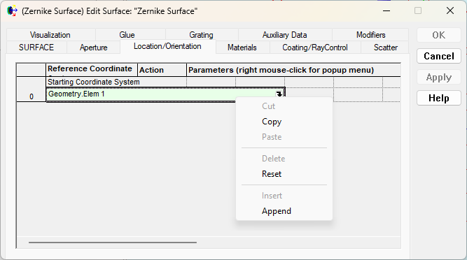
As shown in the surface edit dialog below, the position/orientation specifications are entered using a spreadsheet style interface. Right mouse clicking in the spreadsheet area brings up a context menu containing the allowed operations to perform on the operation list (cut, copy, paste, delete, reset, insert or append).
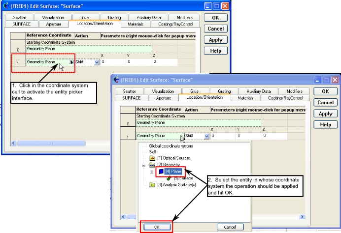
Each row in the operation list represents a single transformation being applied to the entity. At minimum, the operation list must contain the starting coordinate system for the entity (Geometry.Plane in the image above). Each additional operation is defined by the coordinate system in which the operation is applied, the operation type, and the corresponding parameters for the operation. The interface for specifying the coordinate system is called the "entity picker", which can be opened by first clicking in the corresponding cell to activate it and then mouse clicking on the arrow on the far right of the cell to expose the menu. These steps are shown below. Notice that the string in the coordinate system cell (Geometry.Plane) follows the standard hierarchy naming convention used in FRED.
If the node number of the entity being referenced is known then a shortcut to using the entity picker shown above above is to simply replace the hierarchical name in the green cell with the node number inside square brackets (e.g. [4]).
The ability to choose coordinate systems for position/orientation operations is incredibly powerful for constructing systems, since it means that the user does not need to know the absolute global coordinates for an entity. The user only needs to know the entity's position relative to some reference coordinate system (another entity, for example). Additionally, this type of relative referencing scheme means that groups of objects can be linked together and moved as an entire assembly while maintaining their relative position with respect to other components in that assembly.
This feature can be accessed by right mouse clicking on a node in the object tree and selecting "Position/Orientation" from the list menu.
The following lists all of the currently available coordinate transformations and a brief description of the parameter settings for each.
This action makes the selected node coincident with the Parent Coordinate System and links the two together.
Moves the local origin of the selected node to the X, Y, and Z positions in the Parent Coordinate system.
Shift the local coordinate system of the selected node by X, Y, and/or Z in the Parent Coordinate System. This transformation is additive. Consecutive rows of Shift X = 2 and Shift X = 2 would move the object 4 units. In the absence of any tilts or rotations, the order of entry is not important.
For simple rotations the local coordinate system of the selected node is rotated about the origin of the X, Y, and/or Z axes of the Parent Coordinate System. The order of entry is important.
For compound rotations, the local coordinate system of the selected node is rotated about the origin of the X, Y, and/or Z axes of the Parent Coordinate System and an option is also available to choose the order of rotation (default is X, then Y, then Z). By default the Euler angles box is unchecked and the rotations are all relative to the coordinate axes of the Parent Coordinate System, which remains stationary (i.e. the rotations are extrinsic).
If the Euler angles box is checked, the second and third rotations are relative to the rotated coordinate axes of the previous operation(s) (i.e. the rotations are intrinsic) using the Euler convention of Shoemake and described in the book Graphics Gems. Note also that when using Euler angles the rotations switch sign to follow the definition commonly found in lens design software, which is often left handed. This makes it easier on those users who entering rotations based on the angles in their optical design files. The rotation matrix formed using the Euler angle option in XYZ ordering is provided below for reference.
Rotate the local coordinate system of the selected node about a shifted point in the Parent Coordinate System. This action results in a tilt and a decenter for non-zero position entries. The order of entry is important.
Rotate about an axis through the origin Rotate the local coordinate system of the selected node about a new axis passing through the origin of the Parent Coordinate System. The new axis is specified by its direction cosines. FRED normalizes the sum X-dir2 + Y-dir2 + Z-dir2 to unity. The default orientation of the new axis is coincident with the Z-axis of the Parent Coordinate System.
Rotate about an arbitrary axis Rotate the local coordinate system of the selected node about a new axis that is coincident with the line connecting the points (X-pos1, Y-pos1, Z-pos1) and (X-pos2, Y-pos2, Z-pos2). The X, Y, and Z positions are referenced to the Parent Coordinate System. The default orientation of the new axis is coincident with the Z-axis of the Parent Coordinate System.
Rotate one direction to another Applies to the selected node the coordinate transformation that sweeps from one direction to another. The start and end directions are specified as direction cosines in the Parent coordinate system. The position entries specify the center of rotation. The Preserve setting is used to determine and to preserve the orientation of the new position vector, so that, for example, the YZ plane is the same in the original and rotated positions.
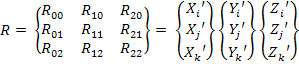
Rotate the local coordinate system of the selected node relative to the Parent Coordinate System using a general rotation matrix and (X, Y, Z) decenter. The entries for the rotation matrix are shown below. The first column contains the (x,y,z) projections of the new X’ axis onto the coordinate axes of the Parent Coordinate System. The second and third columns have similar projections for the new Y’ and Z’ coordinate axes.
FRED does not check to verify that the entries are ortho-normal. This transformation should only be used as a last resort and if the correct input data is readily available. The rotation matrix is applied first, the decenter second.
FRED's coordinate system and handedness FRED operates in a right-handed coordinate system, as shown below. •Positive rotations about the X axis rotate Y to Z •Positive rotations about the Y axis rotate Z to X •Positive rotations about the Z axis rotate X to Y
If the user has entered data in a left handed coordinate system, FRED will manipulate this to a right handed system when conversions are requested. For example consider the following system of three planes:
The orange plane on the left has a right handed (determinant = +1) General Matrix transformation applied, and we observe that the local coordinate axes are drawn right handed. The green plane in the center has a left handed (determinant = -1) General Matrix transformation applied and we observe that the local coordinate axes are drawn left handed. Now, the blue plane on the right had a left handed General Matrix transformation applied and then the "Simplify" option was used on the Position/Orientation dialog. During the simplification request FRED converted the transformation to be right handed and we can see that the local coordinate axes are now flipped with respect to the green center plane.
Changing the Position/Orientation of a node changes the location of all other nodes that are referenced to it either directly or indirectly.
The following rules apply to the re-parent command:
It is strongly recommended that the Re-parent command be the first command issued in the coordinate transformation list as this command negates the operation of any that preceded it.
The coordinate transformations are applied in the order that they are entered, and therefore the order of entry is important. A shift followed by a rotation may not have the same effect as a rotation followed by a shift.
Relative coordinate transformations Coordinate transformations are always applied relative to the Reference or Parent Coordinate System.
The Parent Coordinate System for multiple transformations need not be the same.
Scripting Position / Orientation Manipulating the position and orientation of an object through the scripting language is accomplished by using the T_OPERATION structure and the linear transformation commands. The T_OPERATION structure stores information about a given position/orientation operation in the following structure members:
Type T_OPERATION val1 As Double val2 As Double ... val13 As Double parent As Long type As String End Type
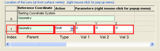
Consider the following position/orientation operations list, which consists of a single "Shift" operation.
There is a direct correlation between the T_OPERATION structure members and the values shown in the GUI interface. In the above example, the structure members correspond to the following entries: type = "Shift" parent = Geometry val1 = 0 ( X-shift ) val2 = 0 ( Y-shift ) val3 = 0 ( Z-shift ) val4..val13 = DO NOT APPLY TO THIS OPERATION TYPE
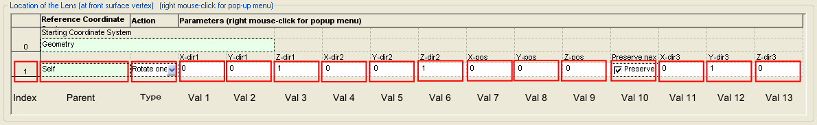
The meaning of val1..val13 is entirely dependent on the value of the Type member of the T_OPERATION structure. For example, consider another operation of the type "Rotate one direction to another" as shown below:
In this case, the structure members correspond to the following entries: type = "Rotate one direction to another" parent = Self val1 = 0 ( X-dir1 ) val2 = 0 ( Y-dir1 ) val3 = 1 ( Z-dir1 ) val4 = 0 ( X-dir2 ) val5 = 0 ( Y-dir2 ) val6 = 1 ( Z-dir2 ) val7 = 0 ( X-pos ) val8 = 0 ( Y-pos ) val9 = 0 ( Z-pos ) val10 = 1 ( Preserve next direction: 1 if checked, 0 if not checked ) val11 = 0 ( X-dir3 ) val12 = 1 ( Y-dir3 ) val13 = 0 ( Z-dir3 )
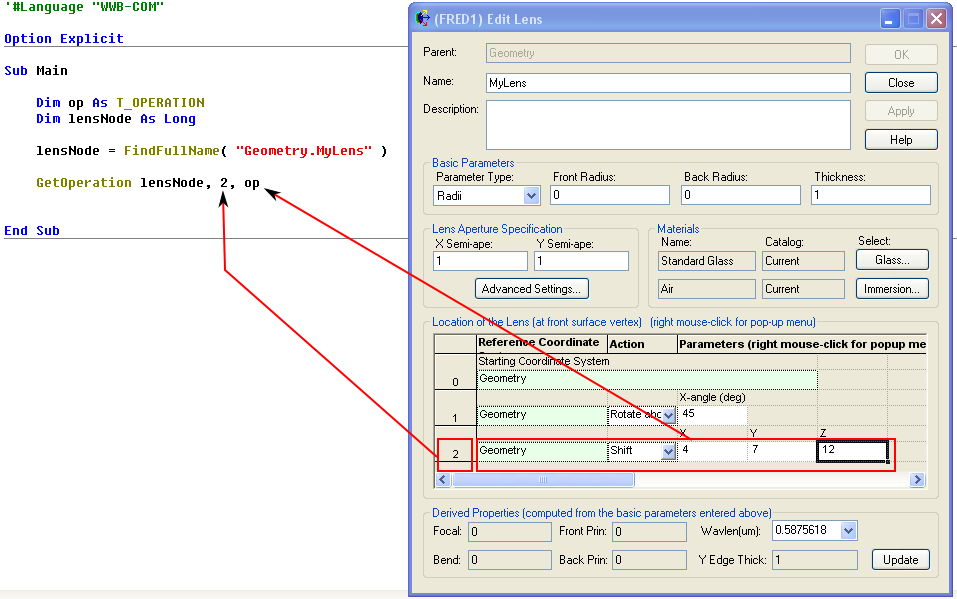
Now that we have established the relationship between the T_OPERATION structure and the GUI position/orientation operations list, lets demonstrate a simple script that retrieves the position/orientation information from a given entity.
The example script above has three simple steps: 1) Dimension the operation structure and node number variable, 2) retrieve the node number of the entity to be queried (in this case MyLens), and 3) retrieve the desired operation information. The last line of the script uses the GetOperation subroutine, which stores the information about position/orientation operation #2 of lensNode in the T_OPERATION structure called "op". In this case the members of the T_OPERATION structure would be:
op.parent = Geometry op.type = "Shift" op.val1 = 4 op.val2 = 7 op.val3 = 12
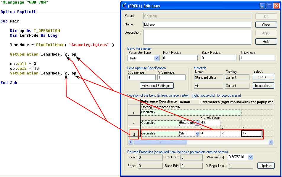
Now consider the following script example in which we retrieve operation information, modify the operation values and then send the operation back to the entity.
In this script we first retrieve the T_OPERATION structure information from operation #2 of lensNode using the GetOperation subroutine, modify the values of the X-shift (op.val1) and Y-shift (op.val2), and then send the modified values back to lensNode operation #2 using the SetOperation command.
Internally, FRED keeps track of the global transformation matrix for each entity in the system. Although this transformation matrix is not generally accessible to the user directly through FRED's scripting language, it is possible to calculate the rotation angles and position using the script provided below (Reference: Decomposing a Matrix into Simple Transformations, Spencer W. Thomas, Graphics Gems II, VII.I). The script works in the following way:
If cos(B) = 0 then,
Sub Main ClearOutputWindow
'convert local axis directions to global 'replace "4" below with node number of entity being queried r11# =1 : r21# = 0 : r31# = 0 r12# = 0 : r22# = 1 : r32# = 0 r13# = 0 : r23# = 0 : r33# = 1 TransformDirection 4, -1, r11, r21, r31 TransformDirection 4, -1, r12, r22, r32 TransformDirection 4, -1, r13, r23, r33
'print out transformation matrix Print "Transformation Matrix: " Print r11 & Chr(9) & r12 & Chr(9) & r13 Print r21 & Chr(9) & r22 & Chr(9) & r23 Print r31 & Chr(9) & r32 & Chr(9) & r33
'compute the x, y and z rotation angles A# = Atn2( r32, r33 ) B# = Asin( -r31 ) G# = Atn2( r21, r11 )
'print A, B and G Print "X, Y, Z Rotation Angles:" Print Chr(9) & "Alpha = " & Chr(9) & RadToDeg( A ) Print Chr(9) & "Beta = " & Chr(9) & RadToDeg( B ) Print Chr(9) & "Gamma = " & Chr(9) & RadToDeg( G )
'print absolute position r11 = 0 : r21 = 0 : r31 = 0 TransformPosition 4, -1, r11, r21, r31 Print "Position (X, Y, Z ): "; Print r11; Print r21; Print r31 End Sub
|
||||||||||||||||||||||||||||||||||||||||||||||||||||||||||||||||||||||||||||||||||||||||||||
.png)
.gif)