|
Description
The Advanced Raytrace is a user-customized raytrace and allows for greater control and flexibility than the standard raytrace methods. With this feature, the user has the ability to perform a raytrace with the following options:
•Perform non-sequential raytracing using hierarchical (standard) or linear ray intersection searches.
•Perform sequential raytracing with a user-defined or FRED calculated raytrace path.
•Perform a raytrace where rays are propagated N intersections
•Perform a raytrace where rays start on surface X and/or stop on surface Y
•Can specify whether rays are stopped in their incident state or whether they reflect/refract at the requested stop surface
•Can trace active sources or trace currently defined rays in the ray buffer
•Can trace all rays or trace every N'th ray in the buffer from ray #X to ray #Y
•Record raytrace path data during the current trace and/or merge data into existing path information
•Record ray history data for the purpose of redrawing raytrace paths
•Suppress the surface incident/absorbed power calculation on surfaces during the raytrace
•Suppress ray surface scattering during the raytrace
•Suppress raytrace summary information from being reported to the output window
•Draw every N'th ray to the 3D view or suppress ray drawing completely
•Apply a ray selection filter after the trace to automatically delete or deactivate rays from the ray buffer
Navigation
This feature can be accessed in the following ways:
•Menu > Raytrace > Advanced Raytrace
•Ctrl + Shift + A
•On the toolbar, press this button: 
Controls
|
Control
|
Inputs / Description
|
Defaults
|
|
Raytrace Method
|
|
Non-sequential with hierarchical search
|
This algorithm is FRED's default raytracing mode. See the hierarchical search application note below for an explanation of this search algorithm.
|
Selected
|
|
Non-sequential with linear search
|
See the linear search application note below for an explanation of this search algorithm. This algorithm is generally not used except for debugging model setup problems.
|
Not selected
|
|
Sequential raytrace using raytrace path #
|
In this raytrace mode, FRED will trace the specific sequence of events defined by a current path in FRED's raytrace paths table. In order to use this option, a previous advanced raytrace must have been run with the "Determine raypaths" check box selected otherwise an error dialog will appear with the following information:
The desired sequential raytrace will not be performed because no raytrace path was selected, or no paths have been defined.
|
Not selected
|
|
Sequential using a user-defined path:
|
In this raytrace mode, FRED will trace the specific sequence of events specified in the user-defined raytrace path and will ignore any object not specified in the path.
|
No paths defined
|
|
Ray Start/Stop Surfaces
|
|
Specify number of surface intersections
|
When the raytrace is performed, this option specifies the number of intersections that the rays will be propagated. When the number of intersections is achieved, each ray is stopped and remains associated with its current surface.
When this option is used, FRED only traces the rays that currently exist in the ray buffer for that exact number of intersections. The implication here is that any rays which would normally have been generated due to ray splitting in a normal non-sequential trace will not be generated when this method is used.
|
1
|
|
Specify start/stop surfaces explicitly
|
When the raytrace is performed, only rays on the start surface will be traced. If Start is set to "Do not care", then all rays will be traced subject to the "Starting Rayset" specifications.
When the raytrace is performed, rays intersecting the Stop surface will be halted from further propagation. The state of the halted rays is further controlled by the additional settings below.
What to do after the ray intersects the stopping surface:
|
Perform the transmit/reflect operation
|
The rays will be transmitted or reflected at the stopping surface subject to its surface properties. With this option, the stopped rays will be preserved in their "outgoing" state at the surface intersection.
|
|
Do not perform the transmit/reflect operation
|
The rays will halted immediately upon intersection with the stopping surface. With this option, the stopped rays will be preserved in their "incident" state at the surface intersection.
|
|
Start: Do not care
Stop: Do not care
|
|
Starting Rayset
|
|
Traceable sources
|
Existing rays will be deleted and new rays from all active sources will be generated and raytraced.
|
Selected
|
|
Existing rays only
|
Rays that currently exist in the ray buffer will be raytraced.
|
Not selected
|
|
Rays To Be Traced
|
|
All active rays
|
All active rays generated as a result of the Starting Rayset controls will be raytraced.
|
Selected
|
|
Rays numbers from
|
Every Nth ray from the subset of rays beginning at ray number X and ending at ray number Y will be raytraced.
|
Not selected
|
|
Raytrace Options
|
|
Determine raypaths
|
When checked, a database of raytrace path information will be generated. The raytrace path database contains a listing of every unique sequence of events that rays took during the raytrace, which contains information critical to the understanding and presentation of how rays are moved through the system. This path data can be accessed through the Stray Light Report and the Raytrace Paths table.
Merge with existing raypaths after raytrace:
If raytrace paths currently exist in the model and the user has selected "Determine raypaths", this option will be available. Otherwise, this option will be grayed out. When selected, the raytrace paths generated in the current raytrace will be merged into the database of existing raypaths.
Behavior with respect to existing paths:
•If "Determine raypaths" is unchecked AND one of either "Sequential raytrace using raytrace path #" or "Sequential using a user-defined path" is toggled as the Raytrace Method, existing raytrace paths will be preserved. This allows sequential raytraces along an existing path to be performed.
•In all other cases, existing raypaths will be deleted when "Determine raypaths" is unchecked.
|
Unchecked
|
|
Create/use ray history file
|
When checked, ray history data will be recorded during the raytrace. Ray history is simply a log of every (x,y,z) intersection point for every intersection for every ray, which allows raytrace paths to be redrawn in the 3D view upon request. If this option is unchecked, raytrace path data will not be able to be redrawn in the 3D view.
|
Unchecked
|
|
Suppress incident/absorbed power accumulation on all surfaces
|
This option suppresses the surface incident/absorbed power accumulation on surfaces during the raytrace, the consequence of which is that no data is available for the Surface Incident/Absorbed Power analysis function. However, it can also improve the speed of the raytrace since the raytrace engine has to do less work by not recording the incident/absorbed power data.
|
Unchecked
|
|
Suppress ray scattering
|
When checked, no rays will be generated due to surface scattering even if the surface properties of the system geometry support i. This is a useful option for quickly suppressing surface scattering during a raytrace without having to modify the surface property definitions of the system. This feature does not suppress bulk volume scattering within a material.
|
Unchecked
|
|
Output/Drawing Options
|
|
Suppress raytrace summary
|
When the Advanced Raytrace is performed, raytrace summary information (ex. rays traced, elapsed raytrace time, number of threads used, etc.) will not be printed to the output window when this option is toggled. This can help to keep the output window "clean" by reducing the amount of information reported.
|
Unchecked
|
|
Draw every N'th ray
|
When toggled, the traced rays will be rendered in the 3D view. Note that this will force the raytrace to be single threaded. When N=1, all traced rays will be rendered. Otherwise, every N'th ray being traced will be rendered in the 3D view.
|
Checked
|
|
Ray Selection Filter
|
|
Apply ray selection filter to the ray buffer at raytrace completion
|
When checked, the defined ray selection filter will be applied to the rayset at the conclusion of the raytrace and the rays will either be deleted from the buffer or marked as inactive. Application of a ray selection filter and using either the Delete or Set Inactive options can increase the speed of ray post-processing for subsequent analyses such as Irradiance, Intensity, etc. The effect of this post-trace ray filtering will be most noticeable when the analyses being performed include only a small subset of the total rays that were traced.
|
Delete
|
Rays not satisfying the ray selection filter criteria will be deleted from the ray buffer. Note that this alone does not compact the ray buffer to a smaller size, it only marks those slots in the ray buffer as deleted and has the effect of increasing the speed of ray buffer processing. Once deleted, the ray information is unrecoverable.
|
|
Set Inactive
|
Rays not satisfying the ray selection filter criteria will be marked as inactive in the ray buffer. Inactive rays are efficiently skipped during post-processing analyses such as Irradiance, Intensity, etc., and has the effect of increasing the speed of ray buffer processing. Inactive rays can be re-activated at a later date using the Ray Manipulation Utilities dialog if needed.
|
|
Compress ray buffer
|
This option can be toggled active in combination with either "Delete" or "Set Inactive".
When toggled, deleted rays, or any empty ray slots in the buffer, are removed and the ray buffer is compressed to its most compact size. As a consequence, memory usage is decreased and the time spent to process the ray buffer during analyses calculations (or scripting loops) is also reduced. The effect of ray buffer compression will be most noticeable when the rays of interest represent a small fraction of the total rays traced during the raytrace.
|
Note that this option will not affect the number of paths collected or available for reporting in the Stray Light Report or Raytrace Paths dialogs. It will, however, affect the "filtered" column data in those reports because those column values depend on the existence of the ray data associated with those paths. When rays are deleted or made inactive, the "filtered" column values for the paths associated with those rays will be reduced accordingly.
|
Unchecked
|
|
|
|
OK
|
Perform the Advanced Raytrace and close the dialog.
|
|
|
Cancel
|
Discard settings and close dialog box.
|
|
|
Apply / Trace
|
Perform the Advanced Raytrace and keep the dialog open.
|
|
|
Help
|
Access this Help page.
|
|
Application Notes
Advanced Raytrace Buffer
The Advanced Raytrace uses the same ray buffer as all other trace options except the single raytrace, which has its own temporary ray buffer. Therefore the raytrace results from an Advanced Trace are available to all analysis functions.
Multi-threading Capability
The multi-threading feature is active during the raytrace unless the user has selected “Trace and Render” or “Trace Existing and Render”. When ray rendering is allowed, no multi-threading occurs.
If an advanced raytrace has been performed with the option "Determine raypaths" selected and another advanced raytrace follows this using the "Existing rays only" option, then the raytrace will proceed single-threaded. However, if raytrace paths exist in the raytrace paths table and the "Traceable sources" option is used, then FRED clears the raytrace paths table and the raytrace will proceed multi-threaded.
Hierarchical Raytrace Algorithm
The hierarchical raytrace search algorithm searches the FRED geometry nodes starting with a seed parent node and then works down through the children, grandchildren, etc. until all progeny nodes have been searched. The intersection determination proceeds in the logical manner depicted by the following flowchart.
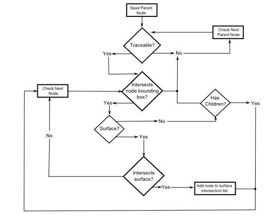
After the algorithm has determined all the surfaces intersected by a ray, the closest surface is chosen as the next surface intersection and the process is repeated for the following intersection. In the hierarchical search algorithm progeny nodes of an untraceable parent node will be ignored.
Linear Raytrace Algorithm
The linear raytrace search algorithm systematically checks every traceable surface node to determine if the ray interests the bounding surface. If the ray intersects the bounding surface, then the algorithm checks to see if the ray intersects the surface. After the algorithm has determined all the surfaces that the ray intersects, the closest surface is chosen as the next surface intersection and the process is repeated for the next intersection.
Two points of distinction from the hierarchical search should be considered:
|
1.
|
This algorithm considers traceable progeny nodes whose parent node is untraceable.
|
|
2.
|
This algorithm does not consider and non-surface nodes.
|
User-defined Raytrace Path
To use the advanced raytrace in this mode a user-defined raytrace path must first be created.
If rays have been traced along a sequential or mixed sequential and non-sequential path and are specified to stop at an intermediate location, then the rays can be traced beyond the intermediate stoppage location by selecting the “Existing Rays Only” option in the advanced raytrace dialog and pressing Apply / Trace (or OK). Alternatively the user can select either "Trace Existing" or "Trace Existing and Render" from the Raytrace menu option or the toolbar.
Raytrace Paths and Merging
Paths and Ray Data
Paths are not equivalent to rays. That is, as a result of path merging you will have path data which reports ray counts and powers that are different than the current set of rays in your system. Suppose, for example, that I trace 10 rays and end up with 5 unique raytrace paths. Then I perform another trace with 10 rays using the merge option and get the same 5 paths. The raytrace path table will show 5 paths and a total ray count of 20 rays, even though I only currently have 10 total rays in my system.
Ray History
The ray history, which allows raytrace paths to be redrawn in the 3D view, is only available for the most recent raytrace. If you have merged raytrace paths from multiple traces then paths may exist which have no rays currently associated with them in the system. Such raytrace paths will not be drawn in the 3D view when the "Redraw ray history" option is selected.
Partial Raytraces
With the Advanced Raytrace feature it is possible to perform "partial" raytraces by either asking for a specific number of intersections or by stopping rays explicitly on an entity. If a partial raytrace has been performed without raytrace paths, it is not possible to continue the existing rays in another trace with paths turned on. Repeated partial raytraces with paths turned on is, however, possible if paths were enabled for all raytrace steps.
Invalid Path Indices
In some circumstances, the following message may be reported when attempting to perform an advanced raytrace with raytrace paths:
Raytrace did not start because raypath accumulation was requested and active rays with invalid path indices were found.
This error message occurs when active, previously traced rays exist in the buffer with raytrace paths that do not match the current raytrace path list. Additionally, rays that have been traced without paths are given a path ID of -1 (i.e. not on a path), which has consequences for path continuation and merging. Consider the scenarios described below.
Suppose that a raytrace has been performed without paths enabled (either a partial or full raytrace) so that at the end of the trace the current rays all have path ID's of -1 and the current raytrace path list is empty. Then, an Advanced Raytrace is performed that attempts to continue the existing rays with paths turned on. In this scenario, the currently existing rays have path ID's of -1 but the path list is empty and therefore the ray path ID's cannot be matched to existing paths and the raytrace cannot proceed.
If a raytrace has been performed with raytrace paths enabled then the rays will exist on paths that match the path list. Next, an advanced raytrace is performed that continues the existing rays with paths enabled again. In this case, the ray's current path ID's match the path list and the paths are continued to be tracked in the raytrace.
When a path merge operation is requested, FRED temporarily deletes the existing paths from the current path list, generates the new path list and then merges the original paths with the new path list. During this merge procedure, when the original paths are temporarily removed from the current path list, there is the possibility for existing rays to have ray path ID's which do not match the current path list (which is temporarily empty before the start of the raytrace). In this scenario, the warning message above will be displayed. The raytrace will only proceed when the previously traced rays are deleted from the buffer, removing the path ID mismatch between the rays and the current path list.
If rays from a source have been created but not traced, then the ray path ID's for these rays is -1. However, these rays have not been raytraced and therefore an Advanced Raytrace using the existing rays with paths enabled will proceed without generating an error message.
Related Topics
Trace and Render
Trace All Sources
Trace Existing Rays
Trace Existing and Render
Trace Single Ray
Delete Existing Rays
Create All Source Rays
User Defined Ray Paths
|
Copyright © Photon Engineering, LLC
|
|