|
Description
This command Performs a single ray trace based on parameters entered in the Single Ray Trace dialog. There are three different ways to specify the single ray to be traced:
|
1.
|
|
A custom ray with user defined starting point and direction.
|
|
2.
|
|
A ray selected from the currently created ray set.
|
|
3.
|
|
A ray selected from a defined source.
|
The third option will create the ray if it does not exist where as the second option only allows selection of rays in the current ray set, i.e. rays that have already been created from the defined and traceable sources.
The single ray trace is handled separately from the ray set created by the document sources. The single ray has no effect on the existing rayset and uses its own temporary buffer, which is lost after the single ray dialog box is closed.
The ray output specified in the single ray dialog box is printed in the Output Window. All of the single ray output data values are absolute and are not relative to a reference ray.
Navigation
This command can be accessed in the following ways:
•Menu > Raytrace > Trace Single Ray
•Ctrl + Shift + 1
•Toolbar button: 
Controls
The single ray trace has three options: Custom Ray, Select Ray From Current Rayset, and Select Ray From Specified Source.
|
1.
|
|
Custom single ray trace where any ray can be defined and traced.
|
|
2.
|
|
Single ray trace from the active ray buffer. The ray set contains only presently created rays.
|
|
3.
|
|
Single ray trace from a specified source. The source does not have to be flagged as traceable. It is not necessary to create the rays first.
|
All three options have the same output specification options and similar ray specification options. Each of the three selection options will discussed separately and the output specification will be discussed in the custom ray section.
Custom Ray
|
Control
|
Inputs / Description
|
Defaults
|
|
Ray Specification
|
|
Custom Ray
|
Specify a custom ray.
|
Checked
|
|
Select Ray from Current Rayset
|
Select a ray from the current rayset.
|
Unchecked
|
|
Select Ray from Specified Source
|
Select a ray from a specified source.
|
Unchecked
|
|
Starting Point: X, Y, Z
|
Define the starting X, Y, and Z position of the ray.
|
0,0,0
|
|
Starting Point Coord Sys
|
Define the coordinate system of the ray's starting point.
|
Global
|
|
Direction
|
Launch the ray along the specified direction vector.
|
Default
|
|
Toward Point
|
Launch the ray towards the specified point.
|
|
|
X, Y, Z
|
Define the X, Y, and Z components of the Direction Vector or Aim Point.
|
0,0,1
|
|
Direction/Toward Point Coord Sys
|
Coordinate system specification for ray aim points.
|
Global
|
|
Wavelength (um)
|
Define the wavelength of the ray.
|
0.5892938
|
|
Immersion Material
|
Define the immersion material for the ray or source.
|
Air
|
|
Polarized
|
Trace a polarized ray.
|
Unpolarized
|
|
Ellipticity
|
If polarized, controls the ellipticity of the polarized light, 1 is circular polarization and 0 is linear polarization. Everything between 0 and 1 is elliptically polarized.
|
1
|
|
Angle (deg)
|
If polarized, angle of the linear or elliptically polarized light with respect to the local X-axis of the source.
|
90
|
|
Coherent
|
Trace a coherent Gaussian beam.
|
Incoherent
|
|
Waist
|
The waist for the coherent beam is located at the starting point with this diameter.
|
2
|
|
Ray Trace Path Strategy
|
|
Drop Down Selection
|
Selection of whether to perform the trace using the standard non-sequential hierarchical search or perform sequential raytracing with a path from the User Defined Paths List.
|
Non-Sequential
|
|
Output Specification
|
|
Position: X, Y, Z
|
Location of the ray at the end of the ray trace in the coordinate system indicated.
|
Checked
|
|
Direction: X, Y, Z
|
Direction of the ray at the end of the ray trace in the coordinate system indicated.
|
Checked
|
|
Surf Nrml: X, Y, Z
|
Surface normal at the location of the ray in the coordinate system indicated.
|
Unchecked
|
|
Angle of Incidence (deg)
|
The angle of incidence of the ray with respect to the surface normal at the point of intersection. Ray angles are reported in degrees. They are always positive.
|
Unchecked
|
|
Angle of Exitance (deg)
|
The angle of the ray with respect to the surface normal at the point of intersection after refraction, reflection, diffraction, or scatter at the surface. Ray angles are reported in degrees. They are always positive.
|
Unchecked
|
|
Suppress Raytrace Summary
|
Do not print summary to output window.
|
Unchecked
|
|
Power
|
The power associated with the ray. See How Power is Assigned to Rays.
|
Unchecked
|
|
Size
|
Gaussian beam waist radius, a coherent option only.
|
Unchecked
|
|
Material
|
Immersion material
|
Unchecked
|
|
Total Path Length
|
The total accumulated optical path length where the optical path length is the index times the actual physical distance.
|
Unchecked
|
|
Previous Distance
|
The ray path length from the previous surface to this surface. This is a physical distance and not an optical path length.
|
Unchecked
|
|
Plot
|
Plot the ray or not.
|
Unchecked
|
|
Phase (waves)
|
This is the absolute phase of the ray and not the relative phase.
|
Unchecked
|
|
Polarization
|
If polarized, the ellipticity, angle, handedness and S-vector components of the resulting polarization is reported.
|
Unchecked
|
|
Pick Ray Color
|
Color of the ray plotted.
|
Unchecked
|
|
Print results in this Coordinate System:
|
Coordinate system of the results reported.
|
Global
|
|
|
|
OK
|
Apply settings and close dialog box.
|
|
|
Cancel
|
Discard settings and close dialog box.
|
|
|
Apply
|
Apply settings and keep dialog box open.
|
|
|
Help
|
Access this Help page.
|
|
Select Ray From Active Ray Buffer
|
Control
|
Inputs / Description
|
Defaults
|
|
Ray Number
|
Define starting (X,Y,Z) position of ray.
|
0
|
|
Position: X, Y, Z
|
Information About the Selected Ray.
|
|
|
Direction: X, Y, Z
|
Information About the Selected Ray.
|
|
|
Power
|
Information About the Selected Ray.
|
|
|
Wavelength (um)
|
Information About the Selected Ray.
|
|
|
Path Length
|
Information About the Selected Ray.
|
|
|
Source
|
Information About the Selected Ray.
|
|
Select Ray From Specified Source
|
Control
|
Inputs / Description
|
Defaults
|
|
Ray Number
|
Select ray number for query.
|
0
|
|
Position: X, Y, Z
|
Information About the Selected Ray.
|
|
|
Direction: X, Y, Z
|
Information About the Selected Ray.
|
|
|
Power
|
Information About the Selected Ray.
|
|
|
Wavelength (um)
|
Information About the Selected Ray.
|
|
|
Path Length
|
Information About the Selected Ray.
|
|
Application Notes
Pre-trace ray propagation
Rays selected from an existing ray set are always propagated to the source wave front before being launched. For example, if the source specification is a planar grid of rays that are being focused to a point, then the source has a spherical wave front centered on the focus point. By definition, every point on the wave front starts with the same phase. The propagation distance is simply a measure of the phase that must be added or subtracted to each ray on the grid so that constant phase at the wave front is maintained. This process is automatic and ensures the accuracy of the raytrace. The propagation distance is reported as the Path Length in the ray information list.
Gratings
During a standard FRED raytrace, the parentage of the rays generated by a grating surface obey the raytrace property assigned to that surface. Typically, the parent ray specifier is the ray with the "Largest incoherent power" and will correspond to the grating order which has the highest efficiency. If ray splitting at the grating surface has been suppressed by the raytrace property, the single raytrace will generate a ray from the first grating order in the efficiency table.
Output Window Reporting
The exact contents of the output window are dependent on which options were selected for output in the Output Specification portion of the single raytrace dialog. However, the output will always list the full name of the surface for each ray intersection event and this listing includes some character codes that will be clarified here. Consider the sample single raytrace output below for a simple system comprised of a doublet, fold mirror and absorbing plane.
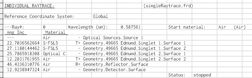
The rows of the output correspond to each of the intersection events that the ray undergoes during the single raytrace and in this example the desired output was angle of incidence at each surface and immersion material at each surface. Note that the third column contains the full name of the corresponding surface for each intersection event but that the surface name is prepended with a combination of T, R, + and - symbols.
FRED's raytrace engine supports many different functionalities (sequential mode, nonsequential mode, single raytrace, advanced raytrace, targeted raytrace, etc.). One of the more unique features of FRED's raytrace engine is the glue algorithm, which supports a complicated logic in order to determine the propagation through a virtual glue layer between optical surfaces. The gluing algorithm introduces an ambiguity in the single raytrace when requesting the ray's immersion material due to "when" exactly the material property is retrieved from the ray during the ray intersection process. Consequently, the + and - symbols in the single raytrace output can be used to identify when this ambiguity occurs.
In the simple example above, the lens element is a doublet comprised of S-FSL5 and S-TIH13 with a glue layer between the two components. In the output, the use of the "+" symbol indicates that the listed material corresponds to the state of the ray after the interaction has occurred. For example, the ray is immersed in S-FSL5 after the ray interacts with Geometry.49665 Edmund.Singlet 1.Surface 1. The use of the "-" symbol indicates that the listed material corresponds to the state of the ray before the surface interaction has occurred and therefore whether the ray will be propagated in Transmission or Reflection following the interaction is ambiguous at the time of the reporting. In the example output you can see this behavior for Singlet 1.Surface 2 and Singlet 2.Surface 1. These two surfaces are, not coincidentally, glued together using FRED's glue algorithm.
Related Topics
Create All Source Rays
Trace All Sources
Trace and Render All Sources
Trace Existing Rays
Trace Existing and Render
Delete Existing Rays
|
Copyright © Photon Engineering, LLC
|
|