This command allows the user to view, edit, and create user defined ray paths. A user defined ray path is a sequential, non-sequential, or mixed sequential and non-sequential series of surfaces that rays intersect as they propagate from its starting point until the ray stops. The ray starting point is either a defined source if the ray has just been created or some other location if the ray has been moved or partially traced. The ray will stop if one of the following conditions occurs:
Sequential Series A sequential series of surfaces in a path indicates that the ray must intersect each surface in the strict order that the surfaces are listed in the series.
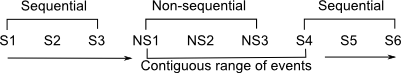
Non-sequential Series A non-sequential series of surfaces in a path indicates that the ray can hit any surface in that particular non-sequential series in any order. The ray leaves a non-sequential series when it intersects the first surface of the sequential series following the non-sequential series. Consider the chart below, where SX indicates a sequential entry in the UDP and NSX indicates a non-sequential entry in the UDP. A group of non-sequential entries and the first sequential entry following that group is a "contiguous range of events". A ray entering this contiguous range will check each surface in the range and intersect the closest surface along its path. The ray exits the contiguous range when it intersects the next sequential surface (S4 in this case), or is halted if it exits the contiguous range without the possibility of intersecting the next sequential surface (S4).
In the UDP below, for example, path entries 2, 3, and 4 make up a non-sequential series. Entries 2, 3, 4 and 5 are therefore the contiguous range of events. A ray in that range will reflect, refract, diffract, and scatter from surfaces within this range until the ray either intersects path entry number 5 or exits the range without the possibility of intersecting path entry 5. If the ray has intersected path entry 5, it will continue continue tracing according to the remaining entries in the UDP.
This command can be accessed in the following ways: •Menu > Raytrace > User-defined ray paths •Ctrl + Shift + U •Toolbar button:
Surfaces that are marked as non-traceable, are available for a user defined path but the rays will stop one surface before the non-traceable surface in a sequential series and ignore the non-traceable surface in a non-sequential series.
The User Defined Ray Paths dialog has a local buffer with a complete replica of all the user defined paths in the FRED document and any paths that have been copied into the local dialog buffer with the Copy button since the dialog was last opened. Until the either OK or Apply button are pushed, these added, deleted, and/or modified paths are not updated into the FRED document. For example, you can open the dialog, delete all the paths, press cancel and no paths will be deleted from the FRED document. But if you press Apply or OK, then all the paths would be deleted.
Until either Apply or OK are pressed, none of the paths in the User Defined Ray Paths dialog are added to the FRED document.
Raytrace control specifications In addition to defining the sequential and/or non-sequential series of surfaces in the path, the user must select the ray control for the ray at each surface. The ray control determines if the ray will transmit or reflect at the specified surface. These ray controls are independent of the ray controls assigned to a surface in the geometry, but they do not override the ray controls assigned in the geometry. For example, if a surface has been assigned FRED's Standard Coating type (96% transmitting, 4% reflecting) and also has the Transmitted Specular raytrace control, then the ray will stop on the surface in question in the UDP if the UDP Ray Control specification was assigned to be Reflect. In this case, the raytrace control specification in the geometry (Transmitted Specular) overrides the UDP ray control specification (Reflect).
In non-sequential path entries, the ray control assigned in the UDP is irrelevant, and the allowed operations are governed by the coating and raytrace controls assigned to the geometry.
The following is an example of a fan of rays that has been traced down a sequential surface path with a “pause/transmit” ray control in the path that pauses the rays on the second surface of a relay doublet.
Paused rays can be continued along the ray path by selecting the “trace existing rays” in the Advanced Raytrace dialog (instead of “delete existing and recreate all sources”), and pressing Apply. The paused rays will then continue to the next pause, the end of the path, or until they cannot hit another surface in the path, which ever occurs first.
|
|||||||||||||||||||||||||||||||||||||||||||||||||||||||||||||||||||||
.gif)
.gif)