|
Description
Element Primitives are commonly used geometries which can be created and modified through a single dialog in the graphical user interface (GUI). Each geometry is completely specified through a minimal set of parameters unique to the element primitive type, and bulk properties can be conveniently assigned to the primitive from the single dialog interface. When created, the element primitive will be added to the object tree as an element primitive parent node with child surfaces that are used to construct the physical geometry.
Why use element primitives? Take as an example the creation of a cube in FRED. As a surface based program, creating a cube from scratch using a custom element would involve individually managing 6 planes, 18 apertures and 1 custom element. In contrast, a cube type element primitive is completely specified in a single dialog by only one parameter (semi-aperture) and FRED internally handles the sizes and positions of the individual planes to ensure a properly closed volume.
The following geometries can be created as Element Primitives:
|

|

|
|
|
Parameters
|
|
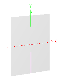
0 - a
|
X semi-aperture
|
|
1 - b
|
Y semi-aperture
|
|
|
Parameters
|
|
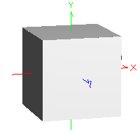
0 - a
|
Semi-aperture
|
|
1 - d
|
Location of origin
|
|
|
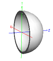
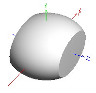
Parameters
|
|
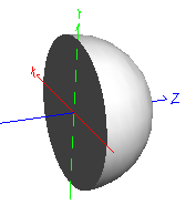
0 - a
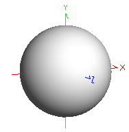
|
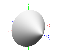
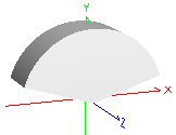
Radius
|
|
1 - b
|
Element origin surface
|
|
2 - c
|
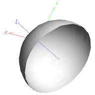
Hemisphere orientation
|
|
|
|

|
.png)
|
|
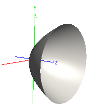
Parameters
|
|
0 - a
|
Semi-aperture
|
|
1 - f
|
Focal length
|
|
|
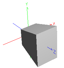
Parameters
|
|
0 - a
|
X semi-aperture
|
|
1 - b
|
Y semi-aperture
|
|
2 - c
|
Z semi-aperture
|
|
3 - d
|
Location of origin
|
|
|
Parameters
|
|
0 - a
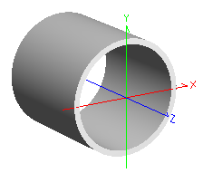
|
Outer radius
|
|
1 - b
|
Wall thickness
|
|
|
|

|

|
|
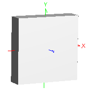
Parameters
|
|
0 - a
|
Full height
|
|
1 - b
|
Full width
|
|
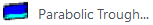
2 - f
|
Focal length
|
|
|
Parameters
|
|
0 - a
|
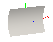
Radius
|
|
1 - b
|
Length
|
|
2 - d
|
Location of origin
|
|
|
Parameters
|
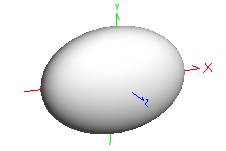
|
0 - a
|
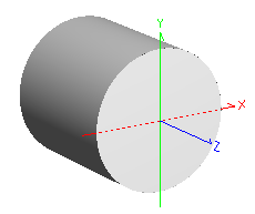
Major radius
|
|
1 - b
|
Minor radius
|
|
|

|

|

|
|
|
|
Parameters
|
|
0 - a
|
Outer radius
|
|
1 - b
|
Wall thickness
|
|
2 - c
|
Length
|
|
3 - d
|
Location of origin
|
|
|
Parameters
|
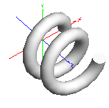
|
0 - a
|
Helix Radius
|
|
1 - b
|
Circle Radius
|
|
2 - c
|
Pitch
|
|
3 - d
|
Number of Turns
|
|
|

|
|

|
|
Parameters
|
|
0 - a
|
X semi-aperture
|
|
1 - b
|
Y semi-aperture
|
|
2 - c
|
Z semi-aperture
|
|
|
Parameters
|
|
0 - a
|
Base semi-aperture
|
|
1 - b
|
Height
|
|
|
Parameters
|
|
0 - a
|
Wedge angle (deg.)
|
|
1 - b
|
Side length
|
|
2 - c
|
Thickness
|
|
3 - d
|
Location of origin
|
|
4 - e
|
Shape of top
|
|
|
|

|
|
|
Parameters
|
|
0 - a
|
X semi-aperture
|
|
1 - b
|
Y semi-aperture
|
|
2 - c
|
Z semi-aperture
|
|
3 - d
|
Z back face
|
|
4 - e
|
Z front face
|
|
|
Parameters
|
|
0 - a
|
Base X semi-aperture
|
|
1 - b
|
Base Y semi-aperture
|
|
2 - c
|
Top X semi-aperture
|
|
3 - d
|
Top Y semi-aperture
|
|
4 - e
|
Depth
|
|
5 - f
|
Type of Element
|
|
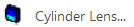
|
Parameters
|
|
0 - a
|
X semi-aperture
|
|
1 - b
|
Y semi-aperture
|
|
2 - c
|
Z thickness
|
|
3 - d
|
Y curvature/radius*
|
|
4 - e
|
Aperture shape
|
|
5 - f
|
Element origin surface
|
|
6 - g
|
Lens orientation
|
*Curvature is the intrinsic property of the Cylinder Lens. If used in an optimization, the value of the variable is interpreted as curvature regardless of the dialog display convention.
|
|

|
.png)
|
|
|
Parameters
|
|
0 - a
|
Parameter A
|
|
1 - b
|
Input Semi-Ape
|
|
2 - c
|
Parameter B
|
|
3 - d
|
Output semi-ape
|
|
4 - e
|
Body of Element
|
|
9 - j
|
Truncated Length
|
|
|
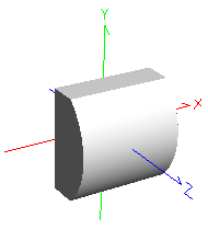
Parameters
|
|
0 - a
|
Semi-aperture
|
|
1 - b
|
Length
|
|
2 - c
|
Location of cylinder surface
|
|
|
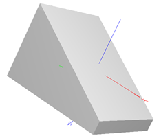
Parameters
|
|
0 - a
|
X semi-aperture
|
|
1 - b
|
Y semi-aperture
|
|
2 - c
|
Bevel Thickness
|
|
3 - d
|
Wedge Angle
|
|
|
.png)
|
|
|
|
Parameters
|
|
0 - a
|
Fiber Core Semi-aperture
|
|
1 - b
|
Outer Semi-aperture
|
|
2 - c
|
Length
|
|
3 - d
|
Location of element origin
|
|
4 - e
|
Cladding Material
|
|
5 - f
|
Core Material
|
|
|
Parameters
|
|
0 - a
|
X semi-aperture
|
|
1 - b
|
Y semi-aperture
|
|
2 - c
|
Hole X semi-aperture
|
|
3 - d
|
Hole Y semi-aperture
|
|
4 - shape
|
Aperture shape
|
|
5 - type
|
Ideal lens type
|
|
See Application Notes below
|
|
|
|
.png)
|
.png)
|
|
|
Parameters
|
|
0 - a
|
Number of sides
|
|
1 - b
|
Semi-Aperture
|
|
2 - c
|
Length
|
|
3 - d
|
Location of element origin
|
|
|
Parameters
|
|
0 - a
|
Number of sides
|
|
1 - b
|
Outer Semi-Aperture
|
|
2 - c
|
Wall thickness
|
|
3 - d
|
Length
|
|
4 - e
|
Location of element origin
|
|
|
Parameters
|
|
0 - a
|
Number of sides
|
|
1 - b
|
Semi-Aperture
|
|
|
.png)
|
.png)
|
|
|
Parameters
|
|
0 - a
|
Number of sides
|
|
1 - b
|
Semi-Aperture
|
|
2 - c
|
Height
|
|
|
Parameters
|
|
0 - a
|
Number of sides
|
|
1 - b
|
Semi-Aperture
|
|
2 - c
|
Length
|
|
3 - d
|
Location of element origin
|
|
|
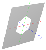
Parameters
|
|
0 - a
|
X semi-aperture
|
|
1 - b
|
Y semi-aperture
|
|
2 - c
|
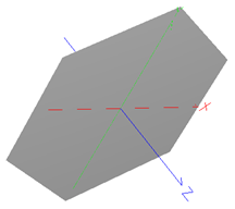
Aperture shape
|
|
3 - d
|
Number of sides
|
|
4 - e
|
Hole semi-aperture
|
|
Navigation
This feature can be accessed in the following ways:
•Menu > Create > New Element Primitive
•On the Geometry folder or a subassembly in the object tree view, right mouse click and select "Create Element Primitive" from the list menu
Controls
|
Control
|
Inputs / Description
|
Defaults
|
|
Parent
|
Parent node of the element primitive.
|
Geometry
|
|
Name
|
Name of the element primitive.
|
Type n
|
|
Description
|
Description of the element primitive.
|
|
|
Geometric Size Parameters
|
|
Values dependent on Element Primitive Type
|
|
Optical Parameters (Initial creation dialog)
|
|
Glass Material
|
Material internal to the element primitive.
|
Air
|
|
Immersion Material
|
Material element primitive is immersed in.
|
Air
|
|
Coating
|
This specification sets both an appropriate coating and corresponding raytrace control set. For example, selecting Transmit sets the element primitive surfaces to have a purely transmitting coating with a transmit specular raytrace control set. Possible combinations of coating/raytrace control sets are:
Absorb: Absorb/Halt All
Reflect: Reflect/Reflect Specular
Transmit: Transmit/Transmit Specular
Bare Surface: Uncoated/ Allow All
|
Depends on element primitive type
|
|
Color
|
Color applied to element primitive surfaces.
|
Depends on element primitive type
|
|
Position/Orientation
|
|
List of position/orientation operations applied to the element primitive.
|
|
|
|
OK
|
Accept settings and close dialog.
|
|
|
Cancel
|
Discard settings and close dialog.
|
|
|
Apply
|
Accept settings and keep dialog open.
|
|
|
Help
|
Open the FRED Help
|
|
Application Notes
Coordinate origin
Certain element primitive types (ex. cube, block, rod, pipe) allow user-specification of the element origin as either the center point of the solid or as a specific surface of the element primitive. When available, this option is listed as a parameter in the Geometric Size Parameters list of the element primitive dialog. This parameter can be very useful for convenient positioning of an element primitive with respect to mechanical references.
Assigning properties after creation
After an element primitive has been created, the dialog functionality is changed for assigning surface materials, coatings, raytrace controls and color. Initially, the "Create New Element Primitive" dialog allows the assignment of materials, coating and visualization color through a set of drop down menus for each property. In the "Edit Element Primitive" dialog, the individual optical parameters drop down menus are replaced by an "Edit Properties" button that gives access to a surface spreadsheet editor.
Assigning global element properties
The following steps should be taken to assign global element properties from the surface spreadsheet editor:
|
1.
|
|
Press the "Edit Properties" button on the Edit Element Primitive dialog box.
|
|
2.
|
|
Set desired properties on a specific row (Row N )of the surface spreadsheet editor.
|
|
3.
|
|
Highlight Row N.
|
|
4.
|
|
Press the "Copy Highlighted Row to All Others" button on the lower left of the dialog box.
|
|
5.
|
|
Press the "OK" button to accept the settings and exit the dialog box.
|
Assigning individual element surface properties
The following steps should be taken to assign properties to the individual surfaces of the element primitive:
|
1.
|
|
Press the "Edit Properties" button on the Edit Element Primitive dialog box.
|
|
2.
|
|
Set the desired materials, coating, raytrace control and visualization color for each surface in the element primitive.
|
|
3.
|
|
Press the "OK" button to accept the settings and exit the Element Surface Properties dialog box.
|
Compound Parabolic Concentrator
The compound parabolic concentrator element primitive can be defined by choosing two parameters, A and B, which uniquely define the CPC geometry.
The available parameters are:
•Input semi-ape
•Output semi-ape
•Length
•Acceptance angle
•Concentration ratio
Some of these parameters are redundant specifications and not all combinations of two parameters yield a unique geometry. The following parameter pairs will uniquely define a CPC geometry, with the remaining parameters being derived:
|
Input semi-ape
Output semi-ape
|
Input semi-ape
Length
|
Input semi-ape
Acceptance angle (deg)
|
|
Input semi-ape
Concentration ratio
|
Output semi-ape
Acceptance angle (deg)
|
Output semi-ape
Length
|
|
Output semi-ape
Concentration ratio
|
Acceptance angle (deg)
Length
|
Concentration ratio
Length
|
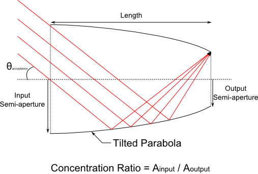
Additionally, the following requirements are placed on the parameter values:
•0 < Input semi-ape < Output semi-ape
•0 < Acceptance angle (deg) < 90
•1 < Concentration ratio
•0 < Truncated length (%) < 100
Cylinder Lens
The Y-curvature parameter on the Cylinder Lens element primitive must be less than or equal to 0.9/Y Semi-ape. This ensures that the lens volume can properly form a closed solid.
Element Reversal (Cylinder Lens and Hemisphere Solid)
The Cylinder Lens and Hemisphere Solid type element primitives are used in the catalog lens import function and therefore have two parameters that allow them to be constructed in a "reverse" sense.
For the Cylinder Lens element primitive, the parameter options allowing lens reversal are:
|
Parameters
|
Description
|
|
5 - f
|
Element origin surface
|
Sets the local origin of the element primitive to either the first surface or the second surface. In the script language, a value of 0 indicates the first surface and a value of 1 indicates the second surface.
|
|
6 - g
|
Lens orientation
|
Specifies which surface, either the Y-toroid or the plane, comes first in the element construction. First, in this sense, is the surface with the smallest Z position value in the local element coordinate system. In the script language, a value of 0 indicates the first surface is the plane surface and a value of 1 indicates the first surface is the Y-toroid surface. Note that toggling this option will automatically change the sign of the Y-Radius parameter.
|
Four different configurations of the origin surface and orientation parameters for a cylinder lens element primitive are shown below.
.bmp)
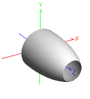
For the Hemisphere solid element primitive, we have the parameter options allowing element reversal are:
|
Parameters
|
Description
|
|
1 - b
|
Element origin surface
|
Sets the local origin of the element primitive to either the first surface or the second surface. In the script language, a value of 0 indicates the first surface and a value of 1 indicates the second surface.
|
|
2 - c
|
Hemisphere orientation
|
Specifies which surface, either the plane or the hemisphere, comes first in the element construction. First, in this sense, is the surface with the smallest Z position value in the local element coordinate system. In the script language, a value of 0 indicates the first surface is the plane surface and a value of 1 indicates the first surface is the hemisphere surface.
|
Four different configurations of the origin surface and orientation parameters for a hemisphere solid element primitive are shown below.
.bmp)
Ideal Lens
Unique construction parameter values (aperture shape, outer semi-aperture, and hole semi-aperture) are stored with each Ideal Lens “type”. Consequently, you may observe that changing the “type” parameter determines whether the surface is a Surface Module type or a Lens Module type. It also changes the values of the outer semi-aperture, hole semi-aperture, and aperture shape parameters.
Related Topics
Create/Edit Lens
Create/Edit Mirror
Create/Edit Prism
Custom Elements vs. Elements
Create - New Element Composite
|
Copyright © Photon Engineering, LLC
|
|