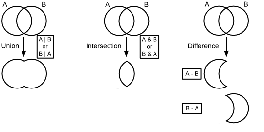
The Element Composite construct allows for the creation of complex solid geometries by application of the union, intersection and difference boolean operations to combine Element Primitives and/or element composites. Once specified, the composite is maintained as a dynamic solid which will update as its component elements are modified. The boolean solid operations are depicted in the diagram below. Please note that only the Difference operation has an order dependency.
The following rules apply to Element Composites:
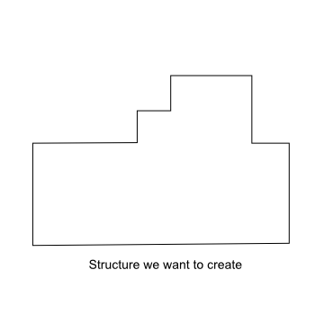
Although the software attempts to repair any coincident surface definitions at the first parent element composite, it is best to avoid surface coincidence altogether. Before constructing the element composite, it is always recommended that possible surface coincidence scenarios be considered for the expected construction method. As an example of potential surface coincidence conflicts, take the thick wall with a varying height profile shown below.
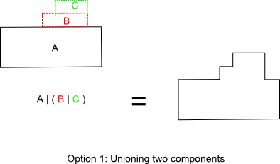
There are at least two ways to create this geometry using element composites. One option would be to create two separate structures (the base and the stepped profile) and union them together.
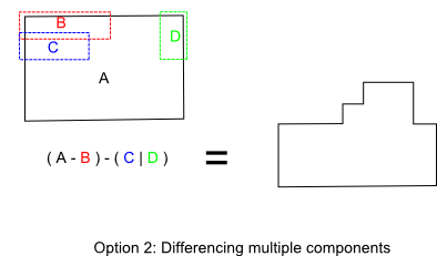
A second option would be to create a base block and trim away the unused portion using difference operators. This option would require more components than Option 1.
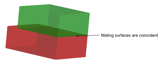
Take a closer look at how Option 1 would be implemented by unioning multiple elements. The first structure, ( B | C ), has four potential coincident surface areas depending on the configuration. When elements B and C are just in contact, the top surface of B and the bottom surface of C are coincident.
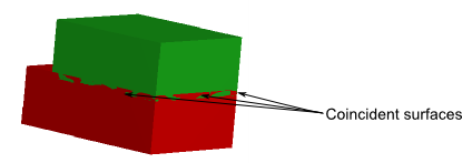
To remove the coincidence at the mating interface, the blocks must then overlap in height. This overlap eliminates the coincidence at the mating interface, but introduces three new coincident surfaces on the block walls.
The surface coincidence issue cascades when the final structure is formed by the boolean operation A | ( B | C ). Similarly, either the mating interface between A and ( B | C ) is coincident or the side walls are coincident. Therefore, Option 1 is only possible if the user is willing to sacrifice precision by slightly under-sizing or over-sizing the component elements in order to eliminate the surface coincidence. Although Option 2 requires managing an additional component, the geometry can be constructed precisely to size without coincident surfaces.
This feature can be accessed in the following ways: •Menu > Create > New Element Composite (boolean solid) •On the Geometry folder or a subassembly in the object tree view, right mouse click and select "Create New Element Composite" from the list menu
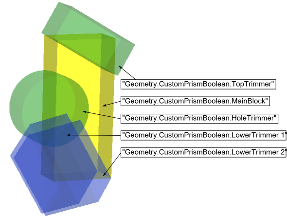
To illustrate the application of element composites, a custom prism is created using boolean operations. Consider the following system composed of five element primitives (four blocks and a rod), which are children of an element composite node called "CustomPrismBoolean". In the image below, the component element primitives are shown in position before applying the logical boolean operations to construct the prism.
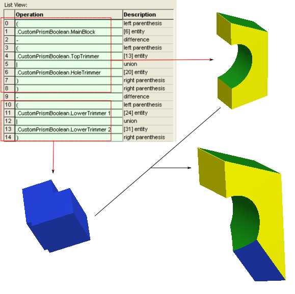
The operation list view for the element composite is shown below. Parenthesis can be used to organize the operations into manageable groups, effectively making each group of parenthesis its own element composite. For example, entries 0 - 9 result in the solid shown in the upper right, created by subtracting the top block and rod from the main body block. Entries 10 - 14 result in the solid shown in the lower left, created by unioning the two tilted blocks (shown in blue above). The completed prism is created by differencing the two parenthetical groups.
Create - New Element Primitive
|
||||||||||||||||||||||||||||||||||||||||||||||||||||||||||||