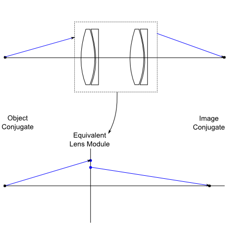
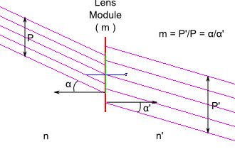
The Lens Module surface types are constructs which can be used to model the effect of a perfect lens system by specification of the focal length and/or magnification (or in the case of a spherical surface, the curvature). Implementation of the Lens Module surface type uses eikonal theory, in which functions are used to describe the optical path length for a ray between reference points in object and image space and which automatically satisfies Fermat's principle. When absolute path length correctness is not required, the Surface Module implementation of an ideal lens can be used. Polarized rays which are incident on a lens module will have their polarization state preserved in the absence of a polarizing coating.
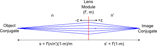
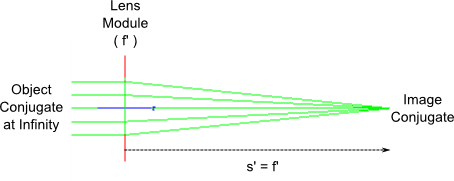
Several rules and assumptions apply to the use of the Lens Module surface types: •Lens Modules can only be used in transmission •The reference planes for the spherical surface eikonal are at the surface vertex •The reference planes for the finite conjugate eikonal are the object and image conjugate planes •The finite conjugate eikonal assumes perfect imaging of the principal points •The reference planes for the infinite conjugate eikonal are the focal planes •The infinite conjugate eikonal assumes perfect imaging of the nodal points
Unlike a physical lens element, Lens Module surfaces have zero thickness. It will be observed that under certain conditions there are discontinuities in the ray positions entering and leaving the lens module surface. This behavior is predicted by geometrical optics, given that the equivalent refracting surfaces for a perfect lens are spherical and centered on the conjugate points. If two perfectly transmitting spherical surfaces centered on the conjugate points are located at the plane of the lens module, the intersection heights at these surfaces for a ray entering and leaving the lens module will be equal. The equal path length requirement for rays passing through a lens module can be verified using a tool such as the ray summary report.
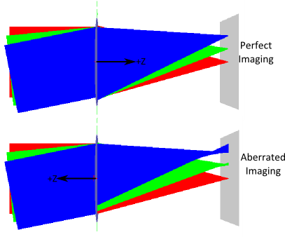
Because the lens modules are based on eikonal theory, they obey the fundamental law that a lens can only have a single perfectly corrected conjugate pair. This rule implies that the lens modules have some directionality associated with their operation. In FRED, the -Z side of the lens module surface is the object side and the +Z side is the image side. Consider the infinite conjugate lens module shown below. In the top case, the object side (object at infinity) is correctly implemented on the -Z side of the lens and the images are perfectly formed for all field angles. In the bottom case, the object side is incorrectly implemented on the +Z side of the lens and the result is aberrated imaging at the detector. The user can quickly identify the +Z and -Z sides of a lens module surface by drawing its local coordinate axes (right mouse click tree menu option).
Some useful references on eikonal theory are: Walther, A., 1995, The Ray and Wave Theory of Lenses. Lambda Research Corporation, OSLO Optics Reference.
This feature can be accessed by selecting one of the following on the Surface tab of a surface dialog box. •Lens Module (Spherical Surface) •Lens Module (Perfect lens with finite FL and nonzero magnification) •Lens Module (Perfect lens with finite FL and infinite conjugate) •Lens Module (Perfect afocal lens)
|