There are four basic "containers" in which entities are stored in FRED, the Subassembly, the Element, the Element Primitive, and the Custom Element.
In general, construction of even the simplest shape requires at a minimum two steps:
Using a plane type element primitive is the simplest and most convenient method of creating a plane surface in FRED, but is not the only method. A plane type element primitive can be created in the following way:
•Menu > Create > New Element Primitive > Plane
The plane surface of the element primitive can be controlled in size, position, and optical properties using the element primitive dialog accessible by double clicking the parent node icon on the object tree.
In this section we will construct the simplest of geometries, a plane.
Step 1: Create a Custom Element In accordance with (1) from above, the first step is to add a Custom Element node to the Geometry folder of the Object Tree. Without first adding a Custom Element we would be unable to create a surface because there would be no place to store it. A new Custom Element can be created in the following ways:
•Menu > Create > New Custom Element •Ctrl + Alt + E •Toolbar button: •On the Geometry folder (or any of its child nodes) in the object tree view, right mouse click and select "Create New Custom Element" from the list menu.
Step 2: Create a Surface Following (2) from above, we can now create a surface in the following ways:
•Menu > Create > New Surface •Ctrl + Alt + F •Toolbar button: •On an Element or Custom Element node in the object tree view, right mouse click and select "Create New Surface".
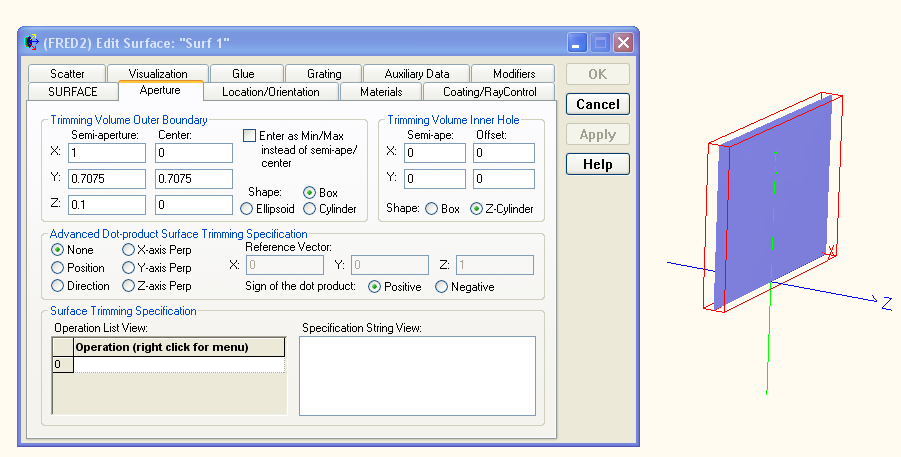
For this simple geometry there are two items of particular importance, the "Type" parameter on the SURFACE tab of the surface dialog and the "Trimming Volume Outer Boundary" specifications on the Aperture tab. As shown, the default surface type is a Plane so we do not need to adjust its settings for this exercise. However, the size and shape of the plane does need to be controlled and can be set using the "Trimming Volume Outer Boundary" specifications. Essentially, we are defining an infinite plane and wish to control its shape and size using some volume (either cylindrical, ellipsoidal or cubic) to trim the boundary of the plane.
The default settings on the aperture tab will create a Trimming Volume Outer Boundary which is 2 units in X and Y diameter and 2 units along Z in depth. By hitting "Apply" and then selecting the newly created surface on the Object Tree (by default this will be "Surf 1" in the custom element node "Elem 1") you will see the bounding volume drawn in red in the 3D view. Notice that if the Trimming Volume Outer Boundary shape is changed from Cylinder to Box on the Aperture tab of the surface dialog that the shape of the plane then becomes a square.
Creating a spherical surface using a custom element is the same as Method 2 for the Plane surface except for an additional step, setting the surface "Type" to be a conicoid. Starting with the plane surface from above, open the surface dialog either by right mouse clicking on the surface node in the object tree and selecting "Edit/View Surface" from the list menu or by simply double mouse clicking on the surface node in the object tree.
On the Surface tab of the dialog, change the "Type" from Plane to Conicoid. New parameter options should be available for specifying the Radius of Curvature and the Conic constant. Enter a value such as -2 as the radius of curvature and hit "Apply". In the 3D view note that the extent (Aperture) of the conic surface is prescribed by the size of the Trimming Volume Outer Boundary.
Using a sphere type element primitive is the simplest and most convenient method of creating a sphere in FRED, but is not the only method. A sphere type element primitive can be created in the following way:
•Menu > Create > New Element Primitive > Sphere
The sphere surface of the element primitive can be controlled in size, position, and optical properties using the element primitive dialog accessible by double clicking the parent node icon on the object tree.
Given that the aperture size of the spherical surface from the Spherical Surface section was determined by the settings of the Trimming Volume Outer Boundary, we should be able to create a sphere by simply increasing the size of the trimming volume. Assuming the surface has a radius of curvature of -2, set the limits of the X, Y and Z semi-apertures to be 4 and hit "Apply".
Although this operation has succeeded in unbounding the spherical surface in order to create a sphere, there is a caveat. The Trimming Outer Boundary serves a second purpose, which is to designate a volume inside of which the raytrace engine must check the surface for a ray intersection point. With this in mind, an unnecessarily large trimming volume will result in an increase in the number of ray intersection checks (i.e. slow down the raytrace).
With a radius of curvature of -2, the resulting sphere has a diameter of 4 and is centered on Z = -2. Therefore, we can size the cylindrical trimming volume appropriately by setting the X, Y and Z semi-apertures = 2 with the Z semi-aperture centered at Z = -2.
Construction of a pyramid requires a completely different approach than that used for the previous sphere example. Here we will demonstrate two different methods of construction, one using four planes with trimming and another using a ruled surface (two connected curves).
The basic approach with this method is the following:
The pyramid being created will have a base width of 2 and a height of 1, so each of the four planes being created should be 2 units wide and 1.415 units in height before tilting.
Step 1: Create the Custom Element As described previously, a Custom Element needs to be added to the FRED document in order to hold the surfaces that will be used to create the pyramid. A Custom Element can be created using the methods described above in Simple Plane.
Step 2: Create the Planes Following the method described above in Simple Plane, after creating the plane surface set the Trimming Volume Outer Boundary to have following specifications:
These settings give a plane whose X semi aperture is 1, Y semi aperture is 0.7075 and centered on Y = 0.7075, Z semi aperture is 0.1 and whose shape is a box. The resulting plane surface is shown on the right of the above image.
Three more planes with identical specifications can either be created by following the same procedure or by simply hi-lighting the surface node in the object tree, copying the node and then pasting it into the custom element.
Step 3: Position the Planes on a Square At this point we have four identical planes all sitting coincident at the origin. These planes will now be positioned along a square which outlines the base of the pyramid. One consideration that should be made during this positioning operation is the orientation of each local surface coordinate system. For consistency we choose to orient each surface such that the local +Z-axis points towards the center of the pyramid. Note that the coordinate system view can be toggled on or off by right mouse clicking on the node of interest and selecting "Coordinate Axes" from the list menu.
Surface position/orientation operations are thoroughly described in the help topic Position/Orientation. Applying a linear transformation can be accomplished in the following ways:
•Right mouse click on a node in the object tree and select "Position/Orientation" from the list menu •Double click on a surface node in the object tree and select the "Location/Orientation" tab on the dialog box •Right mouse click on a surface node in the object tree and select "Edit/View Surface" from the list menu
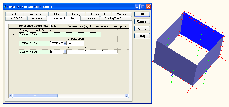
In general, properly positioning each of the four surfaces with the correct orientation will require a rotation about the Y-axis and a shift along either the X or Z axes. Operations can be added, inserted or appended to the operations list by right mouse clicking in the list and selecting the appropriate option from the list menu. An example of the operations list applied to a surface is shown below along with the resulting configuration after all four surfaces have been positioned.
Step 4: Tilt each plane towards the pyramid center Tilting each surface towards the pyramid center requires that each surface has another linear transformation operation appended to its current Position/Orientation list. Unlike the previous operations, this tilt will be applied in the local coordinate of each surface as specified by "Self" in the image below. This coordinate system designation rotates the surface about its own local X axis rather than the axis of Geometry.Elem 1 (the custom element) as used in the previous operations. Shown below is the tilt operation (Rotate about X axis) for a single surface and to the right is the system with tilts applied to each surface.
Step 5: Trim the excess from each surface At this point the base pyramid is constructed but we wish to trim away the unnecessary areas of each plane. This can be accomplished in the Aperture tab of each surface dialog in the "Surface Trimming Specification" section. For a detailed description of trimming operations in FRED, please see the help topics Apertures, Trimming Volumes and Trimming Objects and Trimming Logic.
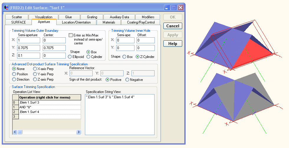
The basic idea is to use local surface normal Z directions in order to specify certain portions of a surface to be removed. For example, the following image shows the trimming specification for "Surf 1" where the local surface normals of "Surf 3" and "Surf 4" are used to designate the portions of "Surf 1" which are removed. To the right of the dialog box are two configurations with "Surf 1" shown in red, the top configuration is the trimmed surface and the bottom configuration is the untrimmed surface.
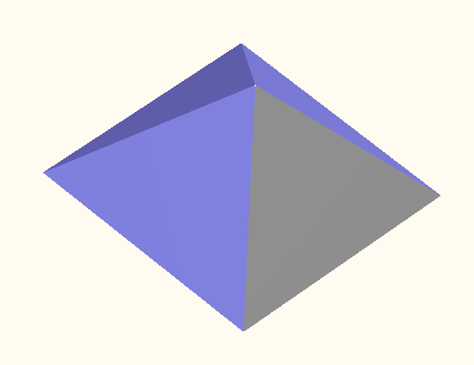
Each of the four surfaces will have a similar trimming specifications list which results in the pyramid structure shown below. Note that if the resulting pyramid has the appearance of being disconnected or ragged, these are results of the tessellation scaling. This can be fixed by right mouse clicking on the custom element node, selecting "Visualization Attributes" from the list menu and then increasing the tessellation.
In this method a ruled surface will be used to construct the pyramid from two curves. The basic approach to this method is the following:
Step 1: Create a Custom Element As described previously, a Custom Element needs to be added to the FRED document in order to hold the curves and ruled surface that will be used to create the pyramid. A Custom Element can be created using the methods described above in Simple Plane.
Step 2: Create Two Curves The ruled surface will be created from the two curves by connecting the two curves with straight lines between points of equal parameterization (see the ruled surface help topic for details). So, before we can create the ruled surface we will create two segmented curves. Segmented curves can be created in the following ways:
•Menu > Create > New Curve •Ctrl + Alt + V •Toolbar button: •On a Custom Element node in the object tree view, right mouse click and select "Create New Curve"
Each segmented curve will have 5 points (0 thru 4), one point for each of the four pyramid corners and the fifth point to connect the first and last points. The first segmented curve will be at Y = 1, the height of the pyramid, and having all five points at Y = 1, X = Z = 0, which defines a single point in space (the tip of the pyramid). The second segmented curve will define the pyramid base. Create two segmented curves defined by the following points:
Step 3: Create a Ruled Surface We can now create the ruled surface from the two segmented curves. A ruled surface can be created in the following ways:
•Menu > Create > New Surface •Ctrl + Alt + F •Toolbar button: •On an Element or Custom Element node in the object tree view, right mouse click and select "Create New Surface"
Choose the two segmented curves as the first and second rail curves in the ruled surface definition. The following square pyramid should result:
Although the second method at first appears to be much simpler, there are situations in which this method should not be used. For example, surfaces created from curves cannot be used to trim other surfaces. Therefore, when this pyramid is used in trimming operations the pyramid should be constructed using the four planes.
Create - New Element Primitive
|