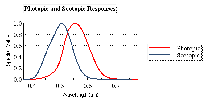
Photometric vs. radiometric units It is possible in FRED to define a source using radiometric units (Arbitrary or Watts) or photometric units (Lumens), the difference being that radiometric units provide a direct measure of energy while photometric units provide a measure of the visual sensation of the energy. This can perhaps be clarified by the spectral response curve of the human eye as shown below (sometimes referred to as the Photopic Response Curve or Relative Visibility Curve).
Clearly, the human visual response is not only wavelength dependent but situationally dependent as well (i.e. bright illumination vs. dark adapted). If we consider the two response curves above we see that under bright illumination the peak eye response is around 0.555 um while the peak response for a dark-adapted eye is around 0.507 um. With this in mind, suppose that we have a hot source which emits some significant radiometric power, say 1,000 Watts. Much of this power will be emitted in the infrared wavelength band at which the response curves above clearly show human vision to be unreceptive. In this case even though the source emits a lot of radiometric power, it does not emit significant luminous flux.
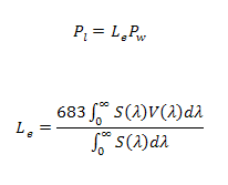
Radiometric to photometric conversion Mathematically the conversion from radiometric units to photometric units involves an integration of the source's spectral power distribution with the photopic spectral response curve,
where Le is the Luminous Efficacy, Pw is the radiometric source power, S(l) is the source spectral power distribution, V(l) is the photopic spectral response curve and Pl is the resulting photometric power. Therefore, in order to accurately convert between radiometric and photometric units, the spectral power distribution of the source should be well sampled, which is facilitated in FRED by using Spectra.
Spectrum are stored in the Spectra folder on the object tree. The Spectra folder can be expanded or collapsed by selecting the "+" or "-" symbol next to the folder in order to display or hide the spectrum currently defined in the FRED document. The related help topic Create New Spectrum explains how to add a new spectrum.
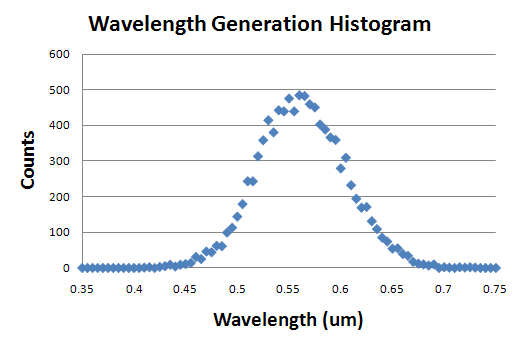
As mentioned above, the accuracy of the photometric unit conversion depends on the sampling of the source spectrum. The method "Random according to spectrum" on the Wavelength tab of a detailed source dialog generates ray wavelengths which statistically follow the spectral power distribution of the spectrum. For example, the following plot is a histogram of the ray wavelengths generated from a source with 10,000 rays using the "Random according to spectrum" method and a photopic response spectrum.
A spectrum node can be created from an IES TM-27-14 definition (XML file format) by right mouse clicking on the Spectra folder and selecting the option, "Import an IES TM-27-14 Spectrum File".
Spectrum can be plotted by selecting a spectrum node on the object tree, right mouse clicking and choosing "Plot" from the list menu. Multiple spectra can be plotted together by holding "Ctrl" while selecting nodes on the object tree. The spectrum plots are dynamic and are automatically updated if changes are made to any of the spectrum being plotted.
A new spectrum can be created from a linear combination of two or more selected spectra. This can be done by selecting two or more spectrum nodes, right mouse clicking and selecting "Sum selected spectra" from the list menu. A dialog will be opened with the following controls:
The linear combination follows the form Dl = aAl + bBl + cCl + ...where a, b and c are the scale factors and A, B and C are the input spectrum. Values outside of a spectrum's wavelength range are zero. If the spectrum is sampled, values inside of the wavelength range and not on a sample point are linear interpolations between the points two closest samples.
Spectra node numbering and looping It is important to note that spectra always retain their original node numbers. When a spectrum is deleted, the remaining spectrum node numbers are not affected and the next spectrum added to the document is assigned the first empty node number in the list. This method of numbering directly impacts the method for looping over existing spectrum nodes. For example, consider the following code:
Sub Main
ClearOutputWindow SpectrumDeleteAllNodes
For ii=0 To 3 spectrumNode = SpectrumCreateBlackbody( 5700, 0.4, 0.7 ) SpectrumSetName spectrumNode, "Spectrum " & ii Next
Print "There are " & SpectrumGetNodeCount & " spectra in the document."
SpectrumDelete 2 Print "Spectrum 2 was deleted!!!"
Print "There are now only " & SpectrumGetNodeCount & " spectra in the document."
spectrumNode = SpectrumCreateBlackbody( 5700, 0.4, 0.7 ) SpectrumSetName spectrumNode, "Spectrum 4"
Print "The most recent spectrum added has node number " & spectrumNode & "."
Print "The spectrum list now looks like this: " For ii = 0 To SpectrumGetMaxNodeNum If SpectrumIsValidNode( ii ) Then Print "Spectrum node " & ii & " has the name " & Chr(34) & SpectrumGetName( ii ) & Chr(34) End If Next
End Sub
This code has the following output:
There are 4 spectra in the document. Spectrum 2 was deleted!!! There are now only 3 spectra in the document. The most recent spectrum added has node number 2. The spectrum list now looks like this: Spectrum node 0 has the name "Spectrum 0" Spectrum node 1 has the name "Spectrum 1" Spectrum node 2 has the name "Spectrum 4" Spectrum node 3 has the name "Spectrum 3"
The text output of this code shows that after spectrum node 2 is deleted from the document, the next spectrum added is assigned the vacant node number. Note that in the last block of the code we used the function SpectrumIsValidNode( ii ) when looping over the possible spectrum nodes. This is important because if we had looped over the nodes without this function the script would halt with an error if the variable ii did not reference a spectrum.
Detailed Source - Wavelengths Tab
|
||||||||||||||||||||||||||||||||||||||||||||