This feature creates a detailed optical source from an IES file according to the ANSI/IESNA LM-63-2002 format. Source ray positions are random volume with dimensions equal to the luminous opening, ray directions are generated randomly according to the intensity distribution and the total power is specified in units of lumens. As values in the IES specification are edge oriented, bilinear interpolation is performed to acquire center oriented values. A spectrum must be used with this source type.
This feature can be accessed in the following ways: •Menu > Create > New Source from IES File •On the Optical Sources folder in the object tree view, right mouse click and select "Create New Source from IES File" from the list menu
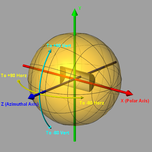
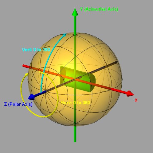
The source photometry type will be listed in the IES File Information section of the source creation dialog. The images below indicate FRED's angle conventions for each of the source types and can be used with a Directional Analysis Entity (DAE) for verification of proper source import and post-creation position/orientation operations. While the IES convention uses azimuthal angles on the range of 0 - 360 degrees, FRED uses azimuthal angles on the range -180 - 180 degrees with the proper interpretation. Photometric zero (all angles = 0 degrees) is along the +Z axis for all photometric source types.
IES Orientation Type A
IES Orientation Type B
IES Orientation Type C
Ideally, a spectrum appropriate for the IES source should be used for ray wavelength generation. However, information regarding the source spectrum is not necessarily available or exactly known. When an accurate spectrum is used for the source, conversions between photometric and radiometric units as well as color image calculations are accurate. In the case where an approximate or inaccurate spectrum is applied to the source, conversions from photometric to radiometric units and color image calculations will not be accurate. Calculations in photometric units will still be accurate.
In this example an IES file from Kim Lighting will be used to create a source for comparison with measured illuminance values for a specified configuration.
Step 1 - Create a spectrum Creating a source from an IES file requires that a spectrum exists in the current FRED document. If no spectrum exists, then a new spectrum will have to be defined before the source can be created.
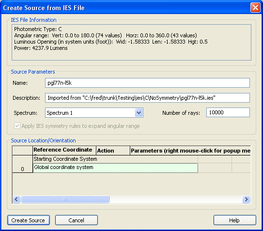
Step 2 - Create New Source from IES File Navigate to: Menu > Create > New Source from IES File. This source will use the file "pgl77n-lk5.ies" available from Kim Lighting. The import dialog indicates the following information about this IES file: Photometric Type: C Angular Range: 117 values over the full sphere Luminous Opening: Cylinder of length 0.5 and full aperture 1.58333. Power: 4237.9 Lumens
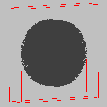
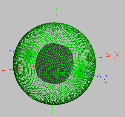
The following detailed source is created in the 3D view. Notice that its ray positions are a random Z-cylinder volume according to the luminous opening definition.
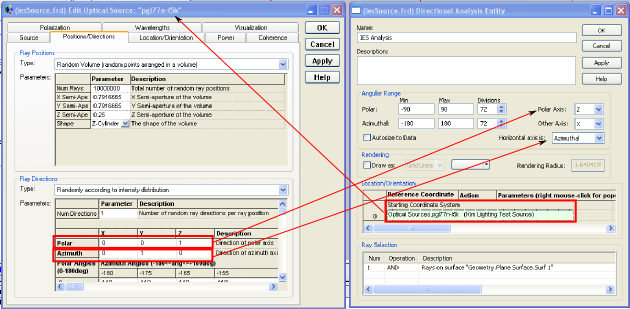
Step 3 - Create a DAE according to photometry type A directional analysis entity can be created with azimuthal and polar angles matching the source's photometry type. This can be useful for visualizing the source orientation and verifying the angular distribution. The source dialog can be used to select the proper polar and azimuthal axes definitions for the DAE. First, the DAE is placed in the coordinate system of the detailed optical source. Then, the polar axis is chosen according to the direction vector specified in the ray directions section of the source while the "other" axis of the DAE is chosen to be the remaining axis not specified by the azimuthal vector of the ray directions (see following image).
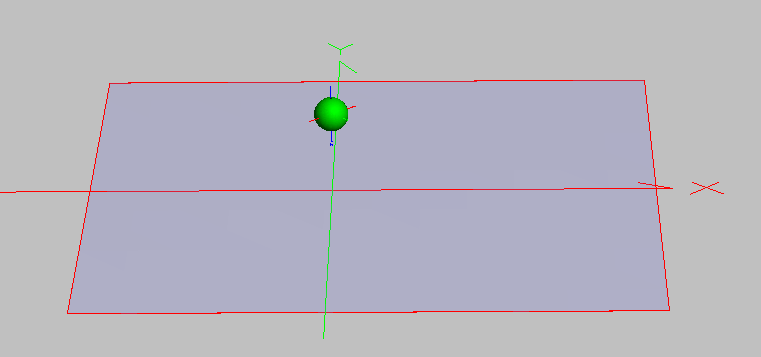
Step 4 - Position source and create illuminated surface This particular IES file comes with measured data from a specific source position/orientation. The source is located at a height of 8 feet above ground with rotation corresponding to a "street side" and a "house side" and a plane surface with approximate aperture dimensions of 64 feet is located at ground level. An analysis plane to be used in the illuminance calculation is assigned to the ground level surface.
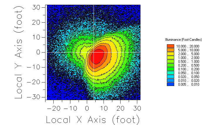
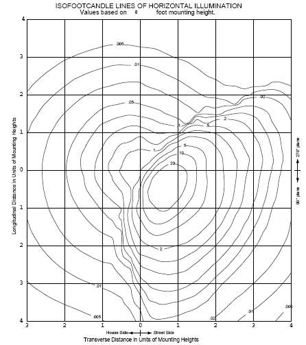
Step 5 - Trace and calculate ISO foot-candle plot With the proper orientation of the source and collection plane now set, the number of source rays was increased significantly to 1,000,000. With the source traced, the illuminance calculation was performed with units of foot-candles and the chart controls specified to use iso-contour lines. The resulting FRED illuminance calculation and the Kim Lighting measurements are shown below. Noise at angles where the intensity values are low is to be expected since fewer rays are generated in these directions.
Analyses - Generate IES Output Directional Analysis Entity (DAE) Ray Directions - Randomly according to intensity distribution
|
|||||||||||||||||||||||||||||||||||||||||||||||||||||||||||||||