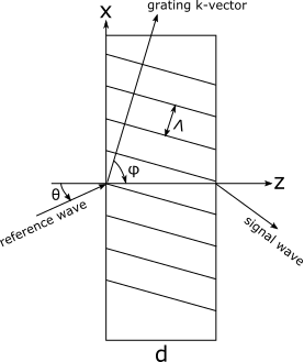
FRED can calculate the diffraction efficiency for volume holograms (Kogelnik, H. (1969). Coupled wave theory for thick holographic gratings. The Bell System Technical Journal 18(9) ) with polarized fields and some modifications that support volume gratings immersed in surrounding media which do not match the emulsion refractive index. Kogelnik's development of the diffraction efficiency for thick volume holograms with sinusoidal refractive index or absorption variations assumes that there are only two significant waves that contribute to the output of the grating; the reference wave (the input wave) and the signal wave (the grating response). Any other diffraction orders are assumed to be small contributors and can be ignored. For a slab of holographic emulsion with thickness d along the z-axis, the field energy along the z direction is conserved (or absorbed, if the material allows it) and the electric field of the signal wave at the entrance or exit face of the grating (for reflection or transmission holograms) can be calculated. The image below represents a thick holographic grating operating in transmission, with the k-vector being perpendicular to the grating fringes.
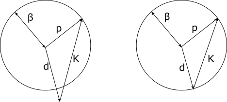
The total electric field within the grating is given by, E = R(z)exp{-i p x} + S(z)exp{-i d x}, with R being the reference wave and S being the signal wave. The direction of the signal wave, d, is related to the direction of the reference wave and the grating k vector through the relationship, d = p - K. When the amplitudes of the variations in refractive index and absorption are small, the propagation constant of the fields inside of the grating becomes b = 2pn/l and the vector d must satisfy b if energy is going to be efficiently transferred from the reference wave to the signal wave. As d increasingly deviates from the b requirement, the diffraction process becomes less and less efficient. Then, we have the following scenarios shown graphically below:
In the graphic above on the left, the vector sum d = p - K does not satisfy the b requirement (i.e. the Bragg condition is not met). In the graphic above on the right, the vector sum does satisfy the b requirement. Therefore, the signal wave for the configuration on the left would have less power than the configuration on the right. In general, the requirement on b means that volume holograms can be very sensitive to angle and wavelength of the incident field.
Kogelnik's theory allows calculation of the electric fields at the input and output faces of the holographic emulsion, with polarization included (both S and P). When an input ray is unpolarized, the assumption is that the ray power is split equally into S and P states and the output ray power will be the average of the S and P field components. The diffraction efficiency is calculated as Pout/Pin, where the power in the output field is proportional to the complex conjugate of the electric field with some additional obliquity factors from the input and output fields.
Some specific notes about application of the volume hologram efficiency specification in combination with FRED's grating types are provided below.
Two point exposure holographic optical element It is recommended that the "Two source user-recorded holographic optical element" be used when applying a Volume Hologram Efficiency specification, as the "user-recorded" implementation is more straightforward to setup than the "Two point exposure holographic optical element" and will include any aberration content of the recording setup. •With the two point holographic exposure grating specification, a signal wave will be generated with the volume hologram efficiency when a ray incident on the grating closely matches either one of Source 1 or Source 2 of the grating specification (keeping in mind the strong selectivity of the volume hologram efficiency with regard to incident angle and wavelength). •Toggling the real or virtual options in combination with the locations/directions of Source 1 and/or Source 2 of the two point exposure grating specification will turn the volume hologram into either a transmitting or reflecting grating. Multiple combinations of the source vectors and real/virtual toggles can result in the same behavior. •The "Ref index" parameter of the two point exposure construction defines the immersion index of the sources that were used to record the hologram. Changing "Ref index" does not affect the volume hologram efficiency calculation. Changing "Ref index" can affect the diffracted signal wave direction. The "Ref index" parameter should generally be set to a value of 1.0.
Two source user-recorded holographic optical element •The grating surface in the FRED model should be immersed inside of a substrate matching the volume hologram emulsion index so that the traced rays are immersed in the emulsion material when interacting with the grating surface (during recording as well as playback).
Linear grating •The orientation and spacing of the phase sheets within the volume hologram are specified explicitly by the settings of the linear grating.
The Volume hologram efficiency specification can be accessed from the Grating tab of a surface dialog. The section on the right hand side of the dialog corresponds to the diffraction efficiency specification for the grating. In the drop-list box, select "Volume hologram efficiency".
|
.png)