|
Description
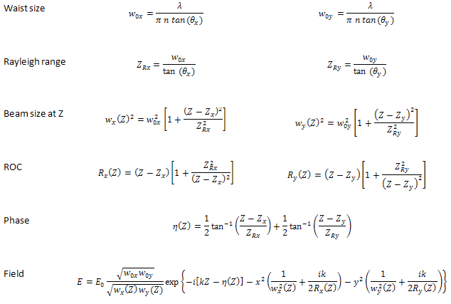
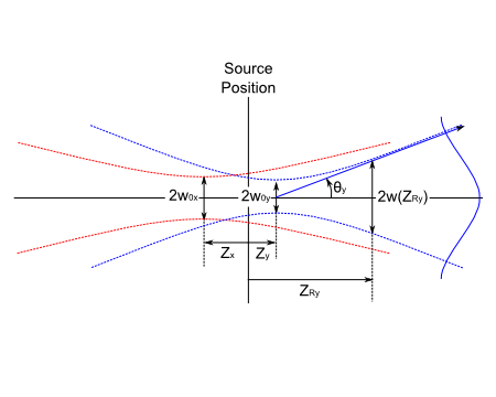
The Laser Diode Beam (coherent) type Source Primitive model represents an ideal Gaussian beam with axial astigmatism that is described by the following equations and schematic.
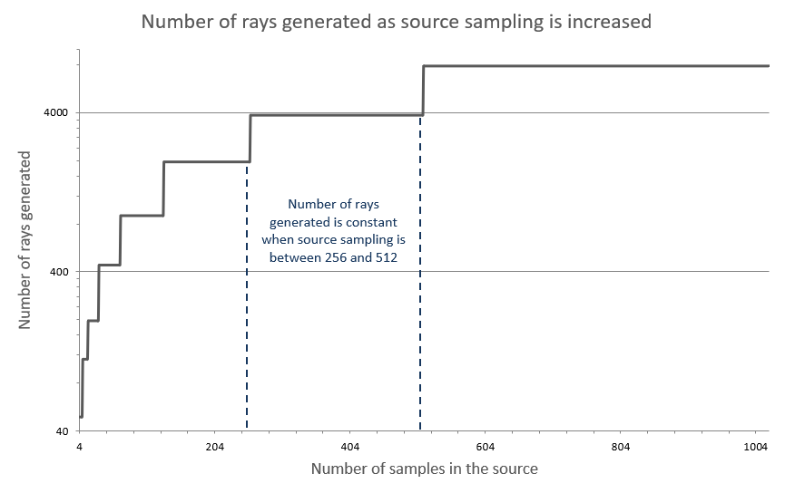
Internally, the field distribution is created using a Coherent Field Synthesis technique to ensure that the field is accurate over the full range of divergence angles between 0 and 90 degrees. Due to the requirements in this field synthesis algorithm, the user will observe that there is a relationship between the required X and Y sampling of the beam and the divergence angle of the source specification with regard to the number of rays generated during source creation. The field synthesis algorithm uses a Fourier transform in order to generate the rayset that properly represents the field and, consequently, the X and Y sampling should be adjusted in powers of 2 in order to jump to the next sampling plateau. For a given sampling specification in the range between 2n - 2n+1, no additional rays will be generated. This behavior is illustrated in the plot below, where the number of samples specified in the source is increased (all other source parameters held constant).
Determining the appropriate sampling rates is a balance between calculation time and field accuracy. A reasonable approach to for determining the number of beam sample points is to place two analysis surfaces in the model, one at the source position and another at the approximate distance of the path length the beam will travel through the optical system. Each analysis surface should filter only rays on the source of interest and be sized large enough to capture the entire beam without clipping (say, 2-3x the beam width). Create the source rays (do not raytrace!) and perform an analysis of the field at each of the two analysis surfaces (i.e. irradiance, scalar field or vector field). For each iteration of this test increase the sampling rates of the source to the next power of 2, checking for integrated power, smooth field profile (no ripple) and beam width. An example of an undersampled field with modulation is shown below in comparison against a properly sampled field.

Reference: Introduction to Optical Electronics, 2nd ed., Amnon Yariv.
Navigation
This feature can be accessed in the following ways:
•Menu > Create > Source Primitive > Laser Diode Beam (coherent)
•Right mouse click on the Optical Sources folder, select Create New Source Primitive > Laser Diode Beam (coherent)
•Toolbar button: .png)
Controls
|
Control
|
Inputs / Description
|
Defaults
|
|
Logical Parent
|
Read-only. Specifies the source's parent node on the tree.
|
Optical Sources
|
|
Name
|
Name of the source as it will appear on the tree view.
|
Laser Diode Beam (coherent) N
|
|
Description
|
Description string that will be visible on the tree view.
|
|
|
Parameter Attributes
|
|
0
|
Total power of the source specified in Watts.
|
1.0
|
|
1
|
Number of sample points across the full width of the beam in the X direction. The total number of rays generated by the source is related to both the number of sample points and the divergence angle, with the number of sampling points being used as a guide for FRED's internal field synthesis routine. It is recommended to change the number of sample points in steps of 2n.
|
8
|
|
2
|
Number of sample points across the full width of the beam in the Y direction. The total number of rays generated by the source is related to both the number of sample points and the divergence angle, with the number of sampling points being used as a guide for FRED's internal field synthesis routine. It is recommended to change the number of sample points in steps of 2n.
|
8
|
|
3
|
Divergence angle of the beam in the X direction whose interpretation is given by parameter 5. Must be a value greater than 0 and less than 90.
|
10
|
|
4
|
Divergence angle of the beam in the Y direction whose interpretation is given by parameter 5. Must be a value greater than 0 and less than 90.
|
10
|
|
5
|
Internally, FRED uses the 1/e semi-angle of the field amplitude when constructing the Gaussian beam. This parameter informs FRED as to the physical meaning of the divergence angle values specified in parameters 3 and 4 of the primitive and allows FRED to convert the supplied angle values to its internal 1/e amplitude semi-angle specification. Width designations using "power" correspond to the power profile of the Gaussian function and those using "amplitude" correspond to the amplitude profile of the Gaussian function.
For example, if this parameter specifies that the user-supplied divergence angles correspond to "Full width at 1/e amplitude", FRED will internally scale the supplied angles by 0.5 in order to arrive at the 1/e semi-angle in field amplitude used internally in the construction of the Gaussian beam.
Variance power specifications (second moment) are typically used for beams with M2 values greater than 1 (see M squared Laser Beam for more information).
|
Half width at 1/e amplitude point
|
|
|
|
|
|
6
|
Offset of the X focal point from the source position in system units. Note that if the focus is moved away from the source position, the number of rays required to properly sample the phase curvature can increase dramatically. As the separation of the focii increases, a larger number of rays are required to properly sample the phase curvature and source creation time is increased.
|
0.0
|
|
7
|
Offset of the Y focal point from the source position in system units. Note that if the focus is moved away from the source position, the number of rays required to properly sample the phase curvature can increase dramatically. As the separation of the focii increases, a larger number of rays are required to properly sample the phase curvature and source creation time is increased.
|
0.0
|
|
Wavelength Attributes
|
|
Single
|
The coherent field will be generated at the requested wavelength. The wavelength units are microns.
|
Default wavelength Preference
|
|
Source Draw Color
|
The ray positions and ray trajectories will be rendered with the selected color.
|
|
|
Polarization
|
|
Polarization
|
If checked, polarization data for the rays is maintained and stored.
|
Unchecked
|
|
Handedness
|
Sets the handedness of the polarization state (relevant for non-linear polarization states). If the ray is propagating towards you, the electric field vector rotates in a clockwise direction for Right handedness and counter-clockwise for Left handedness.
Note that for linear polarization, the application of Left or Right handedness is arbitrary. The user may find that the UI display switches handedness depending on the angle of the linear polarization state entered, but this will have no impact on the resulting representation of the linear state.
|
Right
|
|
Ellipticity
|
Sets the ellipticity of the polarization state, 0 represents linear polarization and 1 represents circular.
|
0
|
|
Angle
|
Sets the angle of the polarization relative to the X axis.
|
90
|
|
|
|
OK
|
Accept settings and close dialog box.
|
|
|
Cancel
|
Discard settings and close dialog box.
|
|
|
Apply
|
Accept settings and keep dialog box open.
|
|
|
Help
|
Access this Help page.
|
|
Application Notes
Detailed Positions Specification
All source models can be edited as a Detailed Source model by right mouse clicking on the source node and selecting, "Edit/View Detailed Optical Source". The detailed ray positions specification of the Laser Diode Beam (coherent) type Source Primitive uses a 1x1 "elliptical" ray grid with specified x and y semi apertures. The values of the x and y semi apertures are computed by multiplying the nominal waist size of the beam by a factor of 2.5. In practice, there should be no reason for the user to edit a Source Primitive as a Detailed Source and this is intended to be informational.
Related Topics
Source Primitives
Plane Wave (coherent)
Point Source (coherent)
Laser Beam (00 mode)
Astigmatic Gaussian Beam
M-Squared Laser Beam (coherent)
|
Copyright © Photon Engineering, LLC
|
|