For an excellent overview on birefringent materials, please see Hecht's Optics, on which the following material is based.
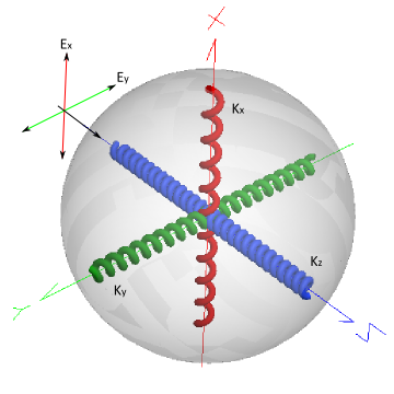
Most optical materials are isotropic, which implies that the effective refractive index is constant with respect to propagation direction within the material. Materials which exhibit anisotropy in their refractive index give rise to unique polarization characteristics which can be used to construct polarization sensitive optical elements. Consider the diagram below which represents a charge shell bound by springs having spring constants; kx, ky and kz. A wave is incident on the system propagating along the Z axis and having electric field components Ex and Ey. The refractive index of the material represented by the spring model is determined by the difference between the E-field frequency and the natural frequency of the spring (related to k) such that stiff springs yield a low index of refraction and weak springs yield a high index of refraction. Assume that in the model below kx > ky. As the Ex and Ey components of the E-field propagate through the medium, the Ex component travels at a faster phase velocity compared to the Ey component. Upon exiting the material, the Ey component of the E-field will be time delayed with respect to the Ex component, potentially changing the polarization state of the outgoing wave field.
In the context of our spring model above, a birefringent material has two spring constants (kx, ky, kz) which are equal to each other. The crystal (represented by an array of these spring models) then has one axis of symmetry (the optic axis) and is said to be uni-axial. If kx = ky in the model above, the z-direction would define the optic axis.
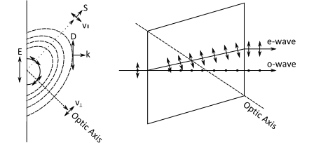
FRED is capable of modeling uniaxial birefringent materials, characterized by two unique refractive index values and a single crystal axis of symmetry. A slice through the crystal material which contains the optic axis is called a principal plane and is useful in understanding the behavior of optical fields as they propagate within a birefringent material. For clarity, the diagrams presented below show propagation in a principal plane of the material. Keeping in mind that the uniaxial crystal refractive index is symmetric about the optical axis, first consider an optical field with an E component in the principal plane as shown in the leftmost diagram below. The incident electric field vector, E, can be decomposed into a component which is parallel to the optic axis one which is perpendicular. Each component of the field sees a different refractive index value and the radiating field expands as an ellipse into the birefringent medium. When representing this field with rays, the rays propagate with a transverse component along a direction connecting the point of emission and the point tangent to the ellipse and normal to the wave vector. The rays which propagate straight through the material are referred to as ordinary rays and those which propagate with the transverse component are referred to as extraordinary rays. Splitting of the incident field into two shifted components is commonly referred to as double refraction. Two principal planes are shown below which depict the elliptical expansion of the extraordinary wave on the left and the ray representation on the right. Electric field vectors drawn as arrows show the component which is in the principal plane and those drawn as dots represent the component perpendicular to the principal plane. The quantities labeled are: E: electric field vector D: displacement vector S: Poynting vector k: wave vector e-wave: extraordinary wave o-wave: ordinary wave
The most commonly encountered anisotropic materials are uniaxial crystals such as calcite, tourmaline, quartz, and lithium niobate. In uniaxial materials, the crystal symmetry is such that two unique refractive index values characterize the material with the terms "ordinary index" (no) and "extraordinary index" (ne) being used to identify them. When the velocity of the ordinary wave travels faster than the extraordinary wave (vo > ve ; no < ne), then the crystal is termed a positive uniaxial crystal. In contrast, if the ordinary wave travels slower than the extraordinary wave (vo < ve ; no > ne), then the crystal is termed a negative uniaxial crystal. The crystal axis is, by convention, a vector pointing along the direction associated with the extraordinary index ne. Some sampled index values at l = 589.3 nm are provided below (ref. Hecht, Optics):
Some birefringent materials are also optically active, meaning that the molecular structure has a handedness, or helicity. Optically active materials can be characterized by two values called the ordinary and extraordinary gyrotropic coefficients. If the material is not optically active, then Go = Ge = 0.0. If the material is an isotropic optically active material, then Go = Ge.
The ordinary gyrotropic coefficient is related to nR and nL, the refractive indices associated with right and left circularly polarized light propagating parallel to the crystal axis. It is also related to the optical rotary power, r, which is the rotation rate (radians per unit length) of the polarization ellipse as a ray propagates parallel to the crystal axis. The mathematical relationships are
Go = 0.5 * (nR - nL) = (l * r) / (2p)
where l is the wavelength measured in the same length units as "r". Ge, the extraordinary gyrotropic coefficient is not well characterized and must be determined by other means. Some examples of optically active materials are crystal quartz, sugar water, and some organic liquid crystals. For quartz Go = 0.00003, Ge = -0.0000576.
This feature can be accessed in the following ways: •Open a materials dialog and select "Sampled Birefringent and/or Optically Active Material" as the type
The bulk properties (that is, the direction of the crystal axis) of the birefringent and / or optically active material determine the polarization modes of the ordinary and extraordinary rays as they propagate inside the material. The effect of the coating is to set the amplitudes and phases of the polarization modes.
In isotropic materials, the relative amplitudes and phases are determined by the well-known Fresnel equations when applied to an uncoated surface. Other well-known formulas are used in the case of a thin-film layer coating. However, for birefringent materials the coefficients are much more difficult to determine. FRED has implemented a theoretical calculation in the case of uncoated surfaces (Bare Substrate coating type) when the source is polarized. Other coating types rely on an approximate heuristic calculation that attempts to reconcile the S and P amplitude coefficients specification of the coating with the coefficients required by the physics of propagating fields inside of the crystal. This approximate calculation is not guaranteed to be accurate. The radiometric error when propagating unpolarized rays (i.e. those not tracking a polarization state) through a birefringent crystal can be significant and doing so is discouraged where radiometric accuracy is required. However, note that in all cases the ray directions will be accurate.
Assigning a Birefringent Material The assignment of a birefringent material to a surface is the same as for any other material type, with the additional issue that the orientation of the crystal axis must be specified in some way. When the birefringent material is assigned by drag/drop on the object tree or through the Materials tab of the edit/view dialog, the coordinate system of the birefringent material is automatically assigned to the parent node of the individual surfaces.
Birefringent Material Coordinate Transformation The coordinate transformation specification of the crystal axis can be verified to ensure that it points in the correct direction at each of the relevant surfaces. This is accomplished by right mouse clicking on the entity and selecting "Edit/View GRIN/Birefringent Material Position/Orientation..." from the drop down menu.
FRED's implementation of uniaxial birefringent materials is derived from "Polarization Ray Tracing in Anisotropic Optically Active Media. I. Algorithms", Stephen C. McClain, Lloyd W. Hillman, and Russell A. Chipman, JOSA A, Vol.10,No. 11, Nov 1993, pp2371-2382
|
||||||||||||||||||||||||||||||||||||||||||||||||||||||||||||||||||