The Faceted Surface is an explicit surface that is represented by a logical connection of vertex positions and can be created from an *.obj or an ASCII *.stl file (*.obj preferred). There is no requirement that the geometry represented in the Faceted Surface represent a single object. In fact, the Faceted Surface can be used to construct an arbitrary number of individual geometry elements but will be stored in FRED's object tree as an individual surface node. Representing multiple geometry elements with a single surface node means that all of the geometry elements will have the same optical properties (coating, scatter models, ratyrace controls). If the Faceted Surface is being used to represent multiple geometry elements, the user may want to verify that the raytrace properties applied to the Faceted Surface node are appropriately set up to allow a sufficient number of multiple consecutive intersections with the same surface.
Faceted Surfaces are also used to support the Data Collector Surface Visualization tool.
This feature can be accessed in the following way: 1.Right mouse click on an existing Custom Element node and choose the option, "Create New Surface". If a Custom Element node does not exist on your tree, you will need to create one. 2.In the resulting dialog, set the surface Type to "Faceted Surface"
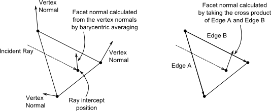
Each vertex position of the Faceted Surface may have a vertex normal vector associated with it, depending on how the data was created. When present, the user will have the option to apply the vertex normals during the raytrace. When using the vertex normals, FRED will calculate the surface normal at the ray's intersection position by performing barycentric averaging on the vertex normals. If the user chooses not to apply vertex normals, a facet normal will be automatically calculated by taking a cross product of the facet edges. The difference between the two surface normal calculations is shown in the graphic below.
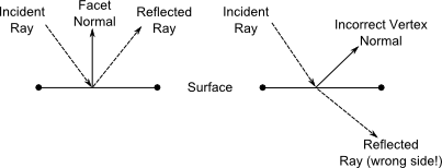
The user should not use the vertex normals on the Faceted Surface unless they are confident in the quality of the vertex normals. Under certain conditions, poor vertex normal data can lead to unphysical scenarios during the raytrace. Consider the scenario below for a faceted surface (shown only in profile) with an incident ray undergoing reflection. On the left, the vertex normals are not being used and FRED calculates a facet normal by taking a cross product with the facet edges. The normal vector is properly calculated and the ray undergoes reflection at the interface. On the right side of the diagram the same surface is setup to use the vertex normals. If the vertex normals are of poor quality, then there is a possibility that the normal calculated at the ray's intercept position will not accurately represent the physical geometry. With a poor quality normal, the ray may well undergo a reflection event that actually brings the ray to the wrong side of the surface! This would potentially show up later on in the raytrace as a material mismatch error.
The Aperture tab of the faceted surface dialog cannot be edited by the user. Specification of the geometry through a collection of organized vertex positions automatically defines the required trimming volume for the surface, which FRED calculates automatically for the user.
The Faceted Surface cannot be trimmed by any other objects. Similarly, the Faceted Surface cannot be used to trim any other objects.
Explicit Surface Script Commands The faceted surface is parameterized internally as an explicit surface type, which means that the explicit surface evaluation scripting commands will execute properly for a faceted surface. However, the values returned should be cautiously interpreted because of the nature of how facets are constructed. If the user requires the explicit surface evaluation routines in order to extract specific information from the faceted surface, please contact Photon Engineering technical support for additional details.
An *frd file can be export to a *.frs FRED script file by navigating to Menu > File > Export > FRED Script Format. For models that contain a faceted surface an *.obj file is written out along with the *.frs file. This file must travel with the *.frs file if the geometry is to be re-built by running the script.
Export Selection as Faceted Geometry
|
||||||||||||||||||||||||||||||||||||||||||||||||||||||||||||||||||||||||