|
|
Navigation: Geometry > Surfaces > Surface Dialog Tabs > Scatter Properties
Scatter Properties
Contact Us: fredsupport@photonengr.com
|
Description
This Scatter tab of a surface dialog allows specification of surface scatter models and scatter importance directions.
This dialog has two sections: Scatter and Scatter Direction Region(s) of Interest. The Scatter portion of the dialog allows creation, editing and assignment of scatter model(s) to be applied to the surface. The Scatter Direction Region(s) of Interest portion of the dialog specifies a solid angle into which rays should be scattered.
Scatter
In the first section, one or more Scatter Properties currently defined in the FRED document can be assigned to the surface. Highlighting the desired property in the Available Scatter Properties list and pressing the Assign button will assign Scatter Properties to the surface. Additionally, the Scatter Properties settings can be edited/viewed and new Scatter Properties can be defined from this dialog. Please see the help for the Create New Scatter Model dialog for more information on how to edit and add new Scatter Properties.
Scatter Direction Region(s) of Interest
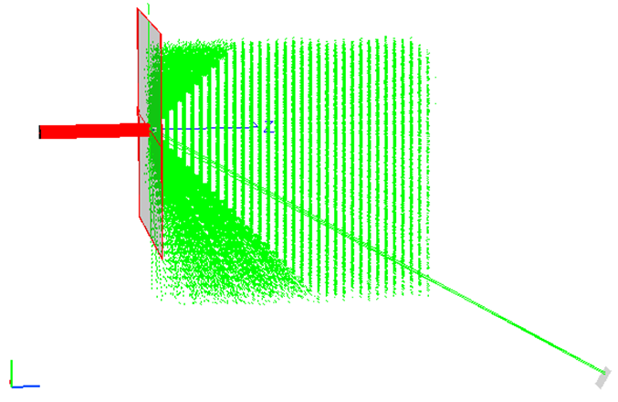
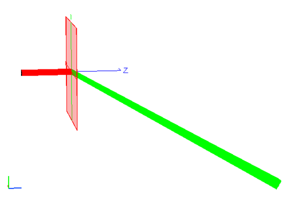
When scattered light is generated at a surface, the Scatter Property(s) assigned to the surface specify how that scattered light leaving the surface is distributed into the hemisphere (either in transmission or reflection). For most modeling applications, only a small fraction of the hemispheric scatter is collected by the detector(s) of the optical system and Scatter Direction Region(s) of Interest allow the user some control over the efficiency of scattered ray generation. Consider the two images below, which show a collimated source ray bundle (red) incident on a scattering plane and scattered light rays leaving the surface (green). A small detector that collects scattered light is located on the bottom right of the images. In the left image, scattered rays (green) are generated into the entire hemisphere leaving the scattering surface but only a handful of the scattered rays are incident on the detector. In the right image, we use a Scatter Direction Region of Interest on the scattering surface to tell FRED that we are only interested in the scattered rays that propagate in the direction of our detector. The result of this specification is that we get many scatter rays statistically sampling our detector and FRED doesn't bother generating rays into the rest of the hemisphere (those rays make no contribution to our detector and therefore have no effect on the analysis).
The power of the rays scattered into the solid angle of interest have the same power they would have been allocated had they been scattered into a full hemisphere (2p steradians) and happened to fall into the same sub-region (i.e. the power is appropriately accounted for by the subtended solid angle). By selecting a solid angle of interest, the same radiometric transfer is achieved but with much better sampling. When applying multiple scatter direction region(s) of interest to the same surface, the radiometric transfer is no longer valid if any of the solid angles overlap. In the overlap areas, the radiometric transfer would be approximately twice the expected value because in the overlap region rays for both selected solid angles carry the correct flux for that region of the total solid angle.
In the Scatter Direction Region(s) of Interest portion of the dialog, pressing the Add New button will open a dialog for setting the solid angle into which rays will scatter from this surface. The solid angle may be described in a number of ways (described in the Controls section below) and are extremely important for setting up a scattering surface efficiently.
Navigation
This feature can be accessed by selecting the Scatter tab in a surface dialog box.
Controls
Scatter model assignment
|
Control
|
Inputs / Description
|
Defaults
|
|
Scatter
|
|
Assigned Scatter Properties
|
Lists scatter properties assigned to this surface.
|
|
|
Assign
|
Assigns a highlighted Scatter Property in the Available Scatter Properties list to the surface.
|
|
|
Remove
|
Removes a highlighted Scatter Property in the Assigned Scatter Properties list from the surface.
|
|
|
Available Scatter properties
|
List of the available defined Scatter Properties. The Scatter Properties listed here are the same as those listed in the Tree. The user may add additional Scatter Properties in this dialog or via the Tree directly using the right click pop-up menu.
|
Black Lambertian, White Lambertian, Harvey Shack.
|
|
Edit/View…
|
Edit/View existing Available Scatter Properties.
|
|
|
Create New…
|
Create new Scatter Properties and add to Available Scatter Properties list.
|
|
|
Scatter Direction Region(s) of Interest
|
|
List
|
List of the scatter directions or regions assigned to this surface.
|
Default (into 2p steradians forward & backward)
|
|
Remove
|
Removes a highlighted scatter designation in the Scatter Direction Region of Interest list from the surface.
|
|
|
Edit/View…
|
Edit/View existing Scatter Direction Region of Interest.
|
|
|
Add New…
|
Add new Scatter Properties and add to Scatter Direction Region of Interest list.
|
|
|
|
|
OK
|
Accept settings and close dialog box.
|
|
|
Cancel
|
Discard settings and close dialog box.
|
|
|
Apply
|
Apply Scatter changes and keep dialog box open.
|
|
|
Help
|
Access this Help page.
|
|
Scattering into a solid angle
|
Control
|
Inputs / Description
|
Defaults
|
|
Name
|
Name of this scattering solid angle to be assigned to this surface
|
ImpSamp1
|
|
Description
|
Informative description of Importance Sampling Specification
|
|
|
Type
|
Drop down menu of the available solid angle descriptions. Available options include:
1.Scatter rays through a closed curve
2.Scatter rays into given direction
3.Scatter rays toward an entity
4.Scatter rays toward a point
5.Scatter rays into the specular direction
6.Scatter rays toward an ellipsoidal volume
|
Scatter rays into a given direction
|
|
Other Data
|
|
Active
|
Sets the flag indicating whether the importance sample is active or inactive. When inactive, no scattered rays will be generated into the specified direction.
|
Active
|
|
Number of scatter rays
|
Sets the number of rays to be scattered into this solid angle per incident ray. For scatter distribution functions where the BSDF value changes rapidly with angle (i.e. peaks in certain directions), more scattered rays may be required to adequately sample the BSDF function. This value will typically range from 10 - 100, depending on the scatter function(s) assigned to the surface.
|
10
|
|
Solid angle scale factor
|
Scales the solid angle so that the target specification is effectively overfilled with scattered rays.
|
1
|
|
Reverse Ray Directions
|
This will reverse the direction of the scatter rays at the time of scatter event. This option is useful when the importance sample target is "virtual" with respect to the scattered rays.
|
Not Selected
|
|
Fractional hole in Solid Angle
|
Allows a central hole in the solid angle to be defined, in effect making an annular solid angle region.
This feature is not functional for "Scatter rays through a closed curve" and "Scatter rays toward and entity".
For importance sample specification types that designate a half-angle parameter, the "Fractional hole in Solid Angle" is a scale factor on the half-angle.
For the ellipsoidal volume importance sample specification, the scattering point sees a boundary curve that is the projection of the ellipsoidal volume. The "Fractional hole in Solid Angle" acts as a scale factor on the semi-major and semi-minor axes of the projected ellipsoidal volume boundary curve.
|
0
|
|
Direction Type
|
Specifies how the importance sample region is statistically sampled by the scattered rays.
The Uniform distribution option uniformly samples the angular region subtended by the importance sample and the individual scattered ray fluxes are scaled proportionally to the BSDF scatter function for a given ray direction. The Uniform option is most useful for BSDF functions that vary slowly with angle.
The Monte-Carlo option statistically biases the individual scattered ray directions according to the BSDF scatter function and each of the scatter rays is assigned the same flux value (i.e. ray density is highest in the direction of peak BSDF). The Monte-Carlo option is most useful when combined with BSDF functions that have narrow peaks in some preferential direction(s) and can significantly improve the ray sampling statistics of the scatter distribution functions in their peak directions. A speed penalty (roughly 2x-5x compared to the Uniform option) will be incurred when using the Monte-Carlo option due to the extra overhead in determining the scattered ray directions.
The flux of an individual scattered ray in monte-carlo mode is determined in the following way:
1. FRED generates 1,000 candidate scattered rays uniformly distributed over the importance region and the total power in these scattered rays is accumulated. If the importance region subtends a hemisphere, then the total accumulated power would be equivalent to the TIS of the scatter model (plus or minus some numerical sampling error). We will refer to the integrated power as X.
2. N scattered rays are requested by the importance sample specification. Of the 1,000 candidate rays, N rays are independently selected with the probability of a given candidate ray's selection being governed by it's direction in the BSDF (i.e. a candidate ray in a region of a high BSDF is more likely to be selected than a candidate ray in a region of low BSDF).
3. Each of the N scattered rays are assigned a flux value equal to X/N.
Because the N rays are probabilistically selected according to their relative BSDF values, it is possible for the same candidate ray to be selected multiple times. Say, for example, that ten scattered rays are requested and that one of the candidate rays is selected three times. Rather than generating the same ray three times, only 8 rays would be generated but one of them would have 3x the power of the others.
|
Uniform
|
|
Scatter Ancestry
|
Specifies a scatter ancestry level requirement on the scattered rays being generated that must be met in order for the importance sample to be applied. The scatter ancestry level requirement can be designated as "greater than", "less than" or "equal to" a specific value.
A specification of "greater than" 0 means that scattered rays will always be generated if the raytrace property allows at least scatter level 1.
Please refer to the help topic on ray splitting and ancestry for more information on ancestry levels.
This option is useful when a scattering surface supports multiple scattering paths that are differentiated by their scatter ancestry. For example, suppose that an analysis is being performed on a telescope baffle and scatter ancestry up to level 2 is of interest. Two importance sample specifications can be assigned to the surfaces of the telescope baffle. The first importance sample would apply to scatter ancestry level 1 and generate rays into the hemisphere (i.e. the baffle scatters back into the baffle assembly). The second importance sample would apply to scatter ancestry level 2 and direct scattered rays into the aperture of the telescope.
|
greater than
|
|
|
|
OK
|
Accept settings and close dialog box.
|
|
|
Cancel
|
Discard settings and close dialog box.
|
|
|
Help
|
Access this Help page.
|
|
Scatter rays into a given direction
|
Control
|
Inputs / Description
|
Defaults
|
|
Angle
|
Semi-angle (deg.) of a cone centered about the specified direction vector.
|
90
|
|
X Y Z
|
Direction vector about which rays will be scattered.
|
0,0,1
|
|
Entity
|
Coordinate system in which the XYZ vector is specified.
|
Global Coordinate System
|
Scatter rays through a closed curve
|
Control
|
Inputs / Description
|
Defaults
|
|
Curve
|
An existing closed curve through which rays are to be aimed.
|
First available curve
|
|
Efficiency vs. Accuracy:
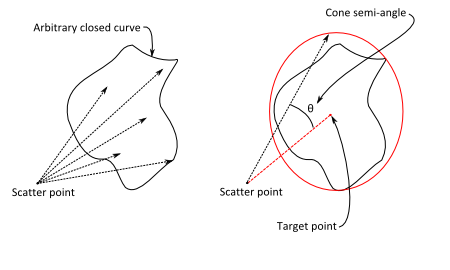
The "Through a closed curve" importance sampling option is designed to accommodate curves with arbitrary path boundaries and there is an approximate calculation that is performed to determine the area enclosed by the curve boundary. This area approximation has an error of ~3%. If the error associated with this calculation is determined unacceptable, the importance sampling specification should be converted to use type "Towards a point". The target point should be the center of the closed curve and the semi-angle should be large enough to encompass the maximum extents of the curve boundary. While the "Towards a point" specification may be less efficient than the "Through a closed curve" specification, it is more accurate. The conversion from "Through closed curve" to "Towards a point" is depicted in the graphic below.
|
Scatter rays toward an entity
|
Control
|
Inputs / Description
|
Defaults
|
|
Entity
|
Entity towards which rays are to be scattered.
|
First entity in list
|
|
The Scatter Rays Toward an Entity scatter direction region of interest specification directs scatter rays toward an entity's limits box (rectangular regardless of the aperture shape) and should be used only when the distance between the scattering surface and the selected entity is large compared to their respective lateral dimensions (i.e. dist2 >> Atarget). As shown in the figure below, each face of the specified entity's limits box which can be seen from the scattering point is split into two triangles in order to determine the scattering direction. Violating the assumption that the distance is large relative to the scattering target area can introduce an unphysical asymmetry in the scattering distribution and introduce significant radiometric error.
Note that in case A the specified entity's aperture is circular, but the scattering solid angle is determined by its rectangular limits box. This will result in a decrease in efficiency since some scattered rays may miss the entity completely. Depending on the geometry it is possible that up to three sides of the limits box can be seen from the scatter point, as shown in case B.
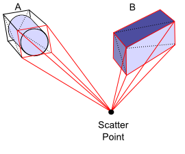
A good rule of thumb to apply is that the half angle of the solid angle cone from the scatter point to the entity's limits box be less than 20o. However, note that accuracy will be improved the larger the distance between the scatter point and the entity.
|
Scatter rays toward a point
|
Control
|
Inputs / Description
|
Defaults
|
|
Angle
|
Semi-angle (deg.) of a cone centered about the Position vector.
|
90
|
|
X Y Z
|
X,Y,Z position of the point to scatter towards.
|
0,0,1
|
|
Entity
|
Coordinate system in which the XYZ vector is specified.
|
Global Coordinate System
|
Scatter rays into the specular direction
|
Control
|
Inputs / Description
|
Defaults
|
|
Angle
|
Semi-angle of solid angle cone centered on the specular direction.
|
45
|
Scatter rays towards an ellipsoidal volume
|
Control
|
Inputs / Description
|
Defaults
|
|
Center
|
Center location of ellipsoid.
|
0,0,1
|
|
X-dir
|
Vector direction specifying ellipsoid's X-axis
|
1,0,0
|
|
Y-dir
|
Vector direction specifying ellipsoid's Y-axis
|
0,1,0
|
|
Semi-Apes
|
Ellipsoid semi-dimensions in X, Y and Z.
|
0.1, 0.1, 0.1
|
|
Entity
|
Coordinate system in which the ellipsoid is specified.
|
Global Coordinate System
|
Application Notes
Multiple importance samples
Multiple Importance Sampling specifications can be assigned to any given surface. However, Importance Sample solid angles that overlap with each other at the same ancestry level will lead to erroneous results because the solid angle in the overlap region is double counted. Each Importance Sampling specification is applied to every active scatter model assigned to the surface.
Default importance sample
All surfaces are created with a default Importance Sampling specification that scatters rays into a hemisphere about the local surface normal. Keep in mind that the default importance sampling behavior is physically correct (BSDF is non-zero everywhere over the hemisphere) but inefficient for raytracing. Although a surface with the Default importance sample specification will generate scattered rays, but, in general, relatively few of those scattered rays will arrive at an analysis plane of interest.
Related Topics
Surface dialog tabs summary
Create a new surface
|
Copyright © Photon Engineering, LLC
|
|