This feature exports FRED geometry or rays to IGES and STEP formats. CAD export capability is under constant development and users are encouraged to send Photon Engineering any test-cases which fail to export from FRED properly. The complex nature with which geometry can be created in FRED does not generically lend itself to direct translation into NURBs.
This command can be accessed by selecting File > Export > CAD (IGES or STEP) Format from the menu.
When exporting current ray trajectories to CAD, users may notice that the ray data (represented as independent curves in the exported CAD file) appears incorrect. The ray trajectory data is extracted directly from the OpenGL (3D viewer) data, which results in certain restrictions and behaviors noted below. Fundamentally, the ray trajectory data is created in CAD as connected line segments, where each segment represents the ray trajectory between ray intersections.
Ray intersection positions appear incorrectly located Graphics display memory, where the ray data is pulled from for export to CAD, is single precision. Consequently, the exported ray intercept data will also be single precision.
Ray trajectories appear incomplete There are two possibilities for this behavior:
The scripted surface and spline surface are not currently handled in the CAD export routine. Recognizable polynomial surface forms described in the application notes below are exported but other unrecognized forms are ignored.
The following table summarizes how surfaces are exported from FRED into CAD format.
The following table summarizes how curves are exported from FRED into CAD format.
In the export dialog FRED users should note the sampling specifications entered for aspheric (Radial Sampling), fitted and ruled (Azimuthal Sampling) surfaces.
Each sampling specification has an important impact on the accuracy of the exported surface as represented by NURBs. Take the case of the cylinder shown in the following figure which was created in FRED as a ruled surface.
In this case we have chosen two circular curves, though in general they need not be of the same shape. Each of the curves is parameterized along its length from 0 to 1 and FRED internally connects points of equal parameterization (A, B, C and D in the figure) with straight lines. One can immediately conclude that the more sampling points specified in the CAD export dialog (Azimuthal Sampling), the more faithfully the original surface will be represented by NURBs. The following image shows exactly this relationship. Shown in the top left is the original surface and shown in the clockwise direction are exported surfaces with sample points of 16, 32 and 128 along the parameterized curve.
In the case of general and toroidal aspheric surfaces there are no exact NURB representations due to the fundamental mathematical relationships and these surface types must be approximated.
For general aspheres, the surface is sampled radially, the samples are connected into a NURB curve, and the curve is spun about the axis to create the three dimensional surface. Like the ruled surface, the number of radial sample points can be specified in the export dialog under the aspheric surface sampling section. As a general rule the approximation becomes more accurate with an increasing number of surface sample points, though there are instances where the local surface shape is such that the slope prohibits such an assumption.
Toroidal aspheres are approximated by projecting a mesh of patches along the z-axis of the surface and smoothing the individual patches at their boundaries. For surfaces which are nearly planar this method works well. However, as the surface becomes increasingly parallel to the direction of the mesh projection (surfaces with significant sag), the mesh cannot sample the surface well and therefore cannot reproduce the surface with high fidelity.
Deformed surfaces are exported if the base surface is a toroidal asphere, XY toroidal asphere, polynomial asphere, Zernike surface, or a bicubic mesh surface. For all other surface types only the base surface is exported to CAD. Depending upon user feedback, deformations added to other surface types may be exported in future versions of FRED. In all supported cases the base surface and the deformation are sampled with a 2D planar mesh and converted to a NURB surface. The accuracy of the resulting NURB is dependent upon the number of U,V patches and the complexity of the deformed surface.
Like most other optical software, FRED does not actually intersect the structures of a diffractive surface. Instead, FRED calculates the local grating frequency at the ray intersection point and uses the grating equation to modify the ray direction accordingly. Since the diffractive structures are not actually described in FRED, they are not exported.
Tabulated cylinder surfaces are formed from curves which are extruded along a straight line. Tabulated cylinders extruded from both continuous and discontinuous curves can be trimmed and exported to CAD.
Cylinder Surface with a Rectangular Cross Section Cylinder surfaces with rectangular cross sections are interesting mathematically because they have branches. Although the outer trimming volume is usually set to trim these branches away, they are nonetheless present. The image below shows two copies of the same square cylinder. The surface on the left has an outer trimming volume which is sized such that the branches are trimmed. The surface on the right has an oversized outer trimming volume and shows the presence of the branches.
In contrast, the CAD export code does not generate branches on cylinders with rectangular cross sections because the NURBs are constructed from points, not mathematical functions. If a cylinder with a rectangular cross section is used as a trimming surface in the FRED model, almost certainly the exported CAD model will be incorrect because of the differences between how FRED and CAD accomplish trimming. In this case, it is recommended that the cylinder be replaced with four planar surfaces in order to be exported correctly.
Where possible, a surface should be trimmed using its inner and outer trimming volume specifications. If the trimming volume options are insufficient for achieving the desired geometry, the rules below should be considered when applying more complex trimming operations.
Trimming in CAD is accomplished when the trimming surface cleanly cuts through the surface to be trimmed. This is very different from FRED, which trims on the basis of the sign of the surface normal. The only exception to this rule are planes, which are internally scaled by 3x during export (but properly trimmed for the final export). If a plane being used as a surface trimmer cleanly cuts through the trimmed object after a 3X scaling, no modification needs to be made to the plane in order to achieve the proper export. Shown below is a cylinder in FRED which is trimmed by a small plane which does not cleanly cut through the cylinder dimensions.
If the cylinder in the previous figure were exported from FRED into CAD the trimming specifications would not export. However, if we increase the extent of the trimming plane so that it completely cuts through the cylinder, then the exported model will include the trimming specifications (see figure below).
Trimming surfaces are created in CAD with their assigned outer trimming volume dimensions, which can lead to incorrect CAD exports because the trimming surface may only partially cut through the base surface. The exception to this are planes, whose dimensions are increased somewhat when used as a trimming surface. Consider the figure below in which a trimming surface that only partially cuts through a base surface will appropriately trim in FRED because the trimming operation is based on the sign of the surface normal. However, the trimmed surface will not export correctly to CAD.
The resulting CAD exports for the case of a plane partially cut through by a trimming surface and for the case of a plane fully cut by a trimming surface are shown below. It is critical to note that the plane only partially cut by the trimming surface does not export correctly to CAD.
Logical Trimming Operation Rules The following rules apply to the export of logical trimming operations: Any number of AND'd surface trimming specifications Any number of AND'd trimming volume specifications Any number of OR'd surface trimming specifications Any number of AND'd aperture trimming curves Any number of AND'd trimming surfaces and aperture curves No mixed AND/OR specifications No trimming specifications with parenthesis
The following rules apply to the export of curve trimming operations:
Export Accuracy and Verification As described in the previous tables, FRED uses fitting routines for several surfaces types because the FRED surfaces do not have exact NURB representations. In the cases of the standard aspheric, general aspheric, and the conic foci surfaces, FRED fits the radial profile to a user-specified number of sample points. By default, the fitting statistics are reported in the output window. The sample points are generated to the maximum radial dimension of the outer trimming volume. If the surface is subsequently trimmed, the printed statistics may not be accurate. FRED output fitting statistics for a standard aspheric surface is shown in the following image.
In the cases of the toroidal, XY toroidal and polynomial aspheric surfaces, the Zernike surface, and the bicubic mesh surface, FRED projects a 2D planar mesh onto the surface and creates a NURB from the sagged mesh. By default, the fitting statistics are reported in the output window. The samples points are generated to the maximum dimensions of the outer trimming volume. If the surface is subsequently trimmed, the printed statistics may not be accurate. FRED output fitting statistics for a toroidal aspheric surface are shown below.
Limitations of the CAD export feature Many optomechanical engineers would like to work in an environment where CAD files containing optical and mechanical structures are seamlessly transferred back and forth between optical and CAD application software. While this is certainly done, we have to be concerned with the underlying accuracy of the NURB representations of the optical surfaces. It turns out that only a few surfaces commonly used in optics have exact NURB representations, including planes, conics, and cylinders. All other surfaces, including aspherics, must be approximated in order to construct a NURB representation.
FRED gives the user the opportunity to set the sampling for the approximated surfaces in the CAD export dialog. Generally speaking, the greater the number of sampling points the closer fit to the surface. However, due to errors in the local surface derivative this may not always be true and there are frequently tradeoffs between the accuracies of the surface points and the accuracies of the surface normals.
The projection method that FRED uses works very well for surfaces that are near planar. On a surface that has significant sag, the mesh can have difficulty conforming to the surface around the sides. Essentially, the mesh is being projected onto a surface that is near-parallel to the projection direction and therefore the surface may not be well sampled.
In many cases, the NURB equivalents created by FRED and other optical engineering software are accurate enough for mount design, solid modeling, etc. However it is our experience that these representations are rarely accurate enough for raytracing if the NURB is brought back into FRED.
In the past, we have recommended to our customers that all optical surfaces expressed as NURBs should be checked before attempting to raytrace in FRED. We typically trace a fan of rays onto the surface and then compare the ray coordinates with the known surface sag values. The differences will be the errors introduced by representing the surfaces as 32 NURBs. Ultimately the user will have to decide if the errors are acceptable for the given application.
In some cases, the error message
"Failure during export!! Attempting to export untrimmed model!"
may occur. This message is displayed when the first attempt at CAD export has failed to apply proper surface and curve trimming specifications. Upon initial failure, a second attempt at model export will be made using only the trimming volumes, ignoring any surface or curve trimming. If this attempt fails as well, the following message will be displayed:
"General failure during export!!"
In some circumstances, the export failure messages may be displayed when trying to export to a remote network location. Exporting the model to a local disk location may resolve the issue. If this does not apply, proceed with the debugging suggestions below.
In the event of catastrophic export failure (on the second attempt), the user should debug the export in the following way. Begin by selecting a high level node on the object tree, perhaps a subassembly containing many other components which is one level below the Geometry folder in the hierarchy. Now open the CAD export dialog and use the option "Export selected entities". If the export proceeded without error, the geometry causing the export failure is not a child of the selected node. Proceed through the object tree working down through the hierarchy until the problem part is identified. If any abnormality with the construction of this part cannot be identified, the user is encouraged to send the sample file to Photon Engineering for further diagnosis.
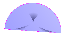
Consider the the following construction of a plane with a semi-circular aperture, which was created by connecting a circular arc with a line segment as a ruled surface. This surface will fail on export from FRED.
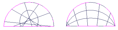
As part of a larger model, this surface was identified as the reason for export failure using the procedure outlined above. Notice that inspection of this surface in the 3D view shows some odd drawing characteristics (the dark regions). It turns out that the two curves being connected were in reverse order, causing the ruled surface to be folded back onto itself. In the following image the original surface is shown on the left and the modified surface connecting the two curves in the proper order is shown on the right, with both surfaces being drawn in iso-contour mode. Notice that the iso-contour lines on the corrected surface (right) are much better behaved than those in the reversed configuration (left). The corrected surface exports properly in FRED.
While FRED is capable of rendering (and tracing) this surface, the NURB representation is probably invalid due to improper surface normals and therefore fails on export.
Element Primitives and Booleans When exporting Element Primitive or Element Boolean nodes, all child nodes will be exported regardless of their traceability flag. The child nodes are necessary for the trimming logic to succeed, though not all of the child nodes are necessarily required for raytracing.
|
||||||||||||||||||||||||||||||||||||||||||||||||||||||||||||||||||||||||||||||||||||||||||||||||||||||||||||||||||||||||||||||||||||||||||||||||||||||||||||||||||||||||||||||||||
.bmp)
.bmp)
.bmp)
.bmp)
.bmp)
.bmp)
.bmp)
.bmp)
.bmp)