The relative orientation and emission characteristics of an illumination source with respect to the entrance aperture(s) of an optical system can affect the efficiency of your raytrace analysis. Consider the scenario below where an optical system with multiple, small apertures is illuminated by a source with an arbitrary radiance distribution. If rays are generated into the entire forward hemisphere (relative to the source), only a small fraction of those rays will enter the optical system through the apertures of interest. Consequently, a majority of the rays generated still need to be raytraced (adding computational overhead) but don’t add any additional information to the analysis being performed (presumed to be within the optical system assembly).
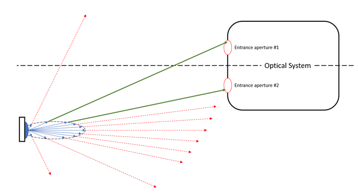
The Acceptance Filter properties of a source allow the user to specify regions into which rays should be generated, thus removing the wasted overhead of creating and tracing rays that will not contribute to the end result. A source with an Acceptance Filter turned on works in the following way. The source’s properties are defined in the usual way by specifying its ray positions, ray directions, power, wavelengths, apodization, etc., in order to describe the radiance of the emitter and produce a set of “candidate rays”. The Acceptance Filter property of the source defines one or more Acceptance Regions as elliptical or rectangular boundary curves in space. Only those candidate rays which pass through the space defined by the combination of all Acceptance Regions will be generated and raytraced. This is shown graphically in the image below, where two elliptical Acceptance Regions have been located at the entrance apertures of the optical system. The dotted red lines show candidate rays that fail to pass through the Acceptance Regions and will not be generated or raytraced. The green lines show candidate rays that pass through the Acceptance Regions and, consequently, will be generated and raytraced. Many candidate rays may need to be defined in the source specification in order to generate a sufficient number of rays meeting the Acceptance Region criteria in order for the apertures to be well sampled.
Individual Acceptance Regions define an elliptical or rectangular boundary curve positioned in any coordinate system in the model. Additionally, the Acceptance Region specifies whether candidate rays directed inside or outside of the boundary will be kept for raytracing.
Determination of whether a candidate ray meets the requirements of the Acceptance Filter as a whole follows from a sequential processing of the individual Acceptance Regions. Processing of the Acceptance Regions proceeds by evaluating each region (from 0 to N) sequentially using the following rule(s).
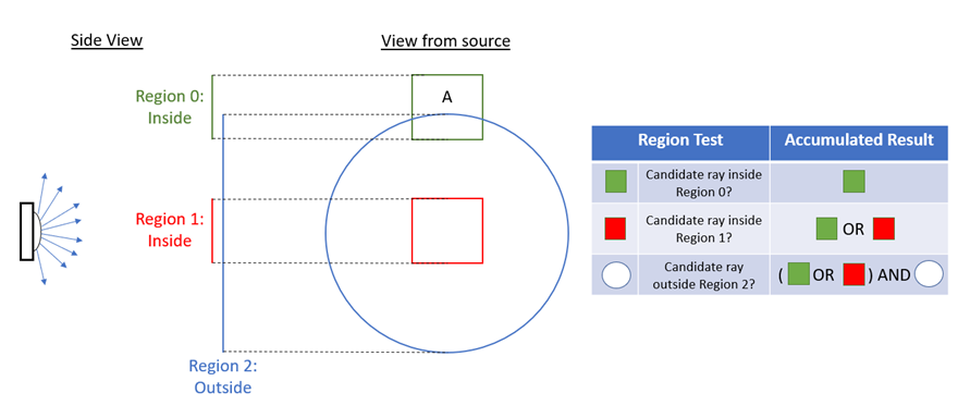
Consider the schematic below, which shows a hemispherically emitting source that has three Acceptance Regions defining its overall Acceptance Filter specification. Region 0 is a rectangle off-axis using the “inside” option, Region 1 is a rectangle on-axis using the “inside” option, and Region 2 is an ellipse on-axis using the “outside” option. The table to the right of the schematic shows how the accumulated result is built up from the previous region tests. In the end, the accepted region is the portion of either Region 0 OR Region 1 that lies outside of Region 2. The final accepted region is marked with the letter “A” on the diagram.
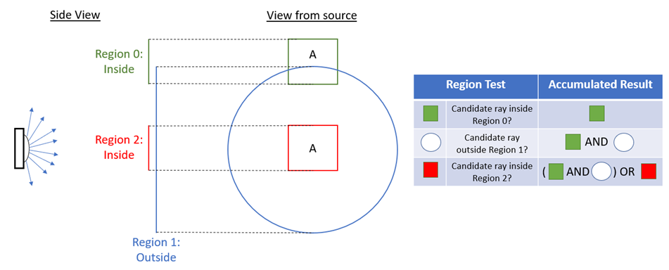
Next, we consider a variation of the previous example in which the ordering of the regions has been changed. The evaluation of the final acceptance filter proceeds in the same manner but the result is different. Here, we see that the final accepted region consists of the portion of Region 0 that is outside of Region 1 as well as the entire inside portion of Region 2. The final accepted regions are marked with the letter “A” on the diagram.
This feature can be accessed by right mouse clicking on a source node and selecting "Edit/View Detailed Optical Source”. Then, select the Acceptance Filter tab in the dialog box.
Active (uncheck for not active): When toggled, Acceptance Filtering is applied during source ray generation. When untoggled, all rays defined by the source will be generated and raytraced. By default, the Acceptance Filter is untoggled for a new source.
Append/Insert/Delete: Right mouse click in the Acceptance Region to bring up a menu that allows new Acceptance Regions to be appended or inserted and existing Acceptance Regions to be deleted. Note that all sources must have at least one acceptance region defined (it can be made inactive) and that if only one acceptance region exists, it cannot be deleted. For an individual Acceptance Region:
When a source node is copied and pasted, the following rules apply regarding acceptance filters:
Co-planar Source and Acceptance Filter Rays at the source which are defined in the same plane as an Acceptance Region will not be created.
All source types have a default, but inactive, Acceptance Region defined. Acceptance Filtering is inactive for a newly created source.
|
.png)