Keywords are a property type in FRED that is intended to help facilitate complex model construction and configuration by acting as pass-throughs for objects which have been assigned a keyword. This property type adds an additional level of organization and control over model configuration on top of the basic organizational hierarchy provided by the object tree structure itself. Furthermore, keywords can be applied to any type of node on FRED's object tree with the exception of Embedded Scripts and Analysis Results Nodes (ARNs).
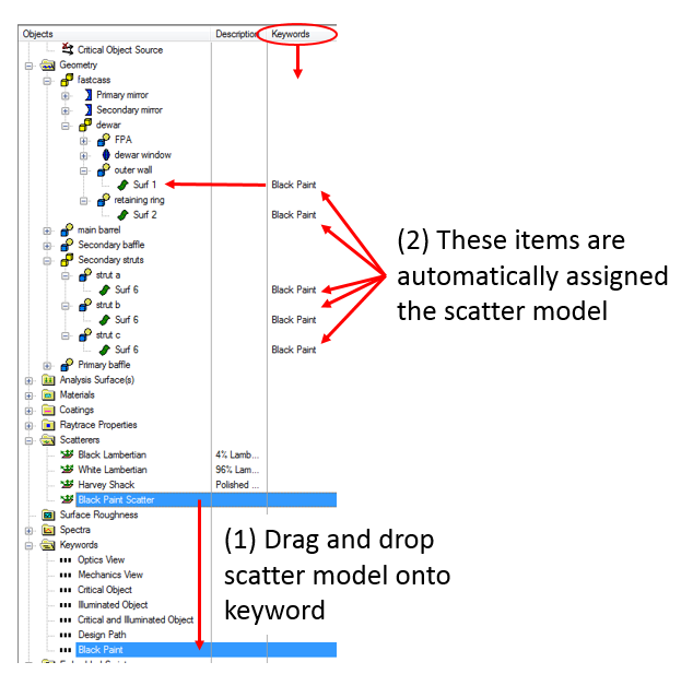
As an example of the basic usage of the keyword property type, consider the scenario shown below where a collection of objects with the same fundamental optical property (painted black, in this case) are not located contiguously on the object tree. Without keywords, the user would have to assign the same set of properties to each individual node; a process that is both prone to operator error and unnecessarily repetitive. With keywords, the operator only has to assign the properties to the keyword itself and each of the objects having that keyword automatically inherit the property assignment.
In the example above, the Black Paint keyword is serving two purposes:
Note that in the images above, the Keywords and Description columns appear to the right of the object tree. The ordering of the Keywords and Description columns can be swapped by simply dragging the column headers to reorder them.
New keywords can be created in the following ways:
Each of these methods adds a new keyword node to the Keywords folder with the name, "keyword n", where n is an integer that is optionally appended to provide a unique keyword name. Once created, you can rename the keyword by selecting it on the object tree and pressing "F2" on your keyboard. The Description field of a keyword node can also be edited by mouse clicking in that column and pressing "F2" on the keyboard. Providing a Description for the keyword is useful for clarifying how the keyword is intended to be used.
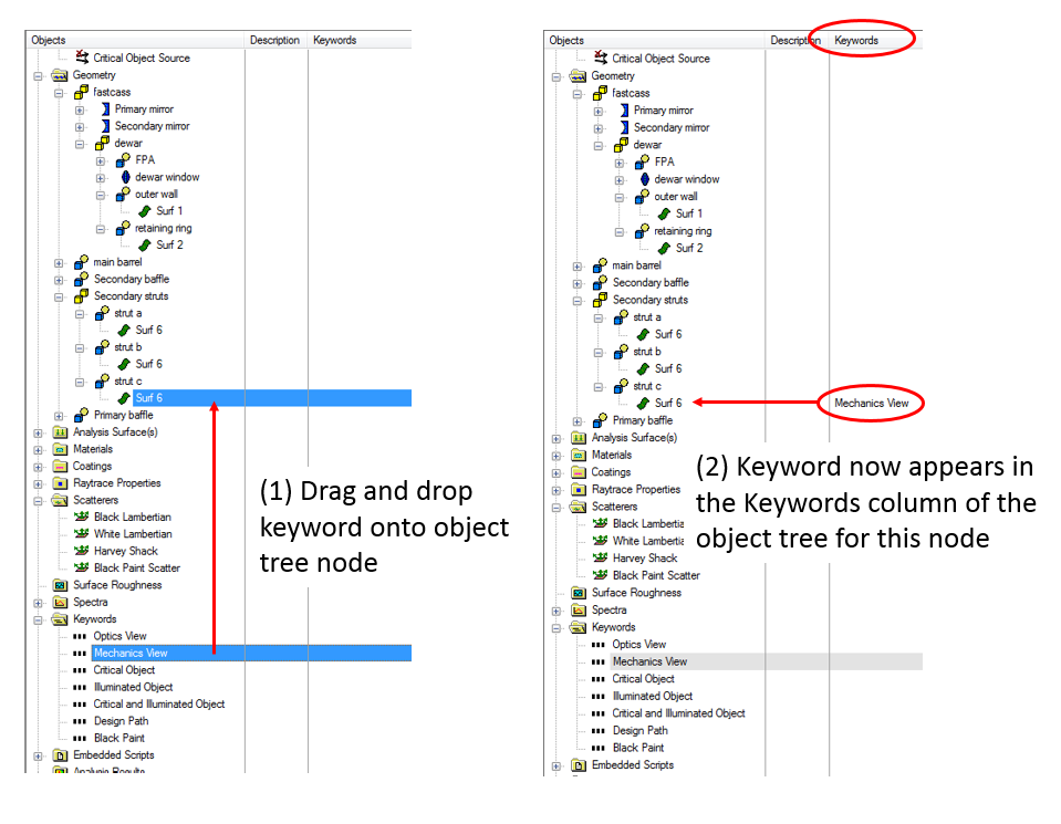
Keywords can be assigned to any node type that is not an Embedded Script or an Analysis Results Node (ARN) and it is important to note that in the case of geometry elements, keywords can be applied to any construct type. Following assignment to an object node, the assigned keywords will be displayed in the Keywords column of the object tree view next to the Description column (you may need to expand the width of the tree view in order to see this column). Keywords can be assigned in a few different ways:
Drag and Drop As with any of FRED's other property types, keyword nodes can be assigned by simple drag and drop on the object tree. In this scenario, a single keyword node can be dropped onto a single node of the object tree and, where appropriate, that keyword is applied recursively to all descendants of the drop target node.
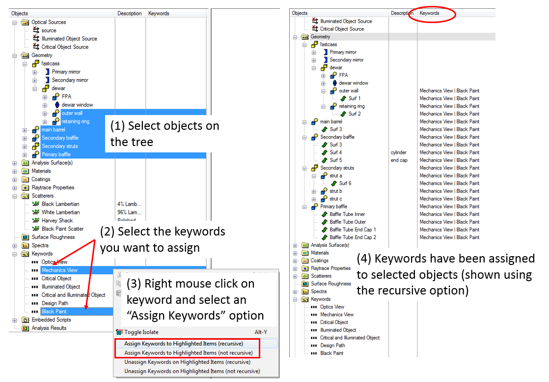
Multiple Tree Selection List Rather than dragging and dropping keywords onto single target nodes, it is possible to form a selection of multiple items on the object tree and then apply one or more keywords to the entire selection list in one operation. To perform this multiple assignment operation:
3D View While no direct route from keyword node to 3D view exists for keyword assignment, it is possible to make use of the 3D view tools in order to facilitate keyword assignments. Suppose, for example that there are objects shown in the 3D view that you wish to select and then assign keywords to. You can take the following steps:
NOTE: this method will only allow you to select surfaces and curves on the object tree, so you will not be able to use this method to assign keywords directly to custom elements or subassemblies, for example.
With the exception of drag and drop, removing keywords from items follows the same basic procedure as keyword assignment.
Multiple Tree Selection List It is possible to form a selection of multiple items on the object tree and then remove one or more keywords to the entire selection list in one operation. To perform this removal operation:
The multiple tree selection list method provides a quick way to clear all of your keyword assignments, for example. Use the SHIFT key on your keyboard to select all of the keyword nodes and then use the CTRL key on your keyboard to add the Geometry folder to the selection list. Then, right mouse click on any of the selected keywords and choose the option, "Unassign keywords on highlighted items (recursive)".
It is possible to perform an isolation operation directly on the keyword nodes so that the 3D view will display only those objects which have the selected keywords assigned (multiple keywords are combined with a logical OR operation). To perform this operation:
It is important to note that if a keyword has been assigned to another property type (coating, raytrace property, etc.) and you isolate based on the keyword, the 3D view will display any objects which currently have that property assigned to them regardless of whether those objects also have the keyword assigned to them. For example, suppose that a keyword called "Black Paint" has been assigned to the coating named "Absorber". Isolating on the "Black Paint" keyword will show any objects which have the "Black Paint" keyword assigned and any objects which have the "Absorber" coating assigned.
Properties such as coatings and raytrace controls can be assigned to objects on the tree by routing them through the keyword nodes rather than individually dragging and dropping properties onto the destination objects themselves. By dragging and dropping a coating onto a keyword, for example, the coating property is then automatically assigned to any surface node which has the keyword assigned to it. This process is illustrated in the image below.
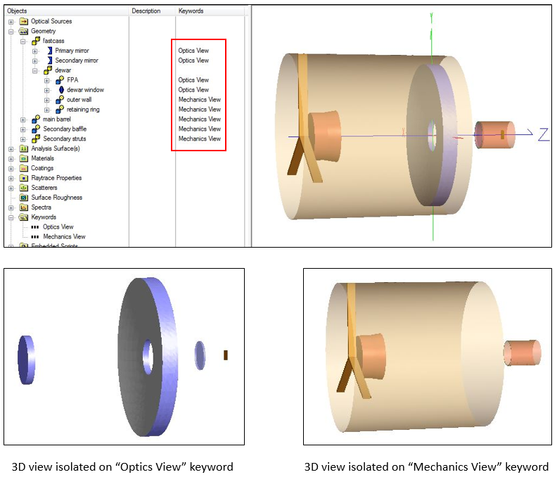
Managing Isolated Views Isolating groups of objects in the 3D view is particularly useful when making modifications to a particular subsystem of a model, redrawing raytrace paths through particular sections, or for generating presentation graphics. In this context, Keywords can be a potentially useful tool for managing different isolated views. For example, consider the simple Cassegrain telescope model shown below, where the keywords "Optics View" and "Mechanics View" have been created and recursively assigned to the components shown in the object tree. This particular scheme assigns the "Optics View" keyword to the optical components defining the imaging path and the "Mechanics View" to the baffle and strut hardware components. By right mouse clicking on one of the keywords and selecting, "Isolate and Fit View to Selection", we can quickly toggle between a view of our optics layout or our mechanics layout, as shown in the pictures below left and right (respectively). Note that you could also show an isolated view of both components together, though in this particular example that reduces back to the complete system.
Critical and Illuminated Objects There is a calculation referred to as a "critical and illuminated object analysis" which is pretty standard when constructing a software model for stray light analysis. The basic concept is to flood the entrance aperture of the system with rays in order to determine which surfaces can be seen from object space and then repeat the process in reverse from the detector in order to determine which surfaces can be seen from image space. Surfaces which can be seen from object space are referred to as "illuminated objects" and those which can be seen from image space are referred to as "critical objects". Surfaces which are both illuminated objects and critical objects are important because they provide direct paths between object space and the detector. For more on this calculation and many other incredibly useful topics in stray light analysis, please contact Photon Engineering about our Stray Light Analysis Short Course.
The script below provides the basic implementation of a critical and illuminated object analysis using keywords as the mechanism for labeling surfaces as critical or illuminated (or both) following the analysis. Following the script execution, the user can isolate the 3D view on the keywords to visually inspect the results of the analysis or run an accompanying script which makes use of the keyword assignments resulting from the critical and illuminated object analysis.
'#Language "WWB-COM" Option Explicit
Sub Main
ClearOutputWindow() EnableTextPrinting(True) Print "Critical/Illuminated Object Analysis Using Keywords" Print ""
'Create (or use existing) three keywords which are used to flag critical 'objects, illuminated objects and objects which are BOTH critical and illuminated Print "Finding keywords to be used..." Dim coKey As Long, ioKey As Long, coioKey As Long coKey = KeywordFind( "Critical Object" ) ioKey = KeywordFind( "Illuminated Object" ) coioKey = KeywordFind( "Critical and Illuminated Object" ) If coKey < 0 Then coKey = KeywordAdd( "Critical Object", "" ) End If If ioKey < 0 Then ioKey = KeywordAdd( "Illuminated Object", "" ) End If If coioKey < 0 Then coioKey = KeywordAdd( "Critical and Illuminated Object", "" ) End If
'Create (or use existing) a keyword which is used to identify optics along 'the nominal design path. We will exclude objects with this keyword from our 'determination of the critical and illuminated objects. Dim designKey As Long designKey = KeywordFind( "Design Path" ) If designKey < 0 Then Print ">>> Design path Keyword not found. Halting." End End If
'Find the sources which are used as the illuminated object source and the 'critical object source Print "Finding sources to be used..." Dim ioSrc As Long, coSrc As Long ioSrc = FindFullName( "Optical Sources.Illuminated Object Source" ) coSrc = FindFullName( "Optical Sources.Critical Object Source" ) If (ioSrc < 0) Or (coSrc < 0) Then Print ">>> Critical or Illuminated object source not found. Halting." End If
'Create two lists which have the same length as the number of entities 'in the model. One list is used during the illuminated object trace and 'the other list is used during the critical object trace. The index into the 'list will be a node number and the value of a given index position will be 'the power incident on the entity for the corresponding raytrace. Initialize 'the values of both lists to -1 and remove from the corresponding entity any 'keywords associted with this calculation. Print "Initializing critical/illuminated object lists..." Dim ioList() As Double, coList() As Double Dim nCount As Long, curNode As Long nCount = GetEntityCount()-1 ReDim ioList( nCount ) : ReDim coList( nCount ) For curNode = 0 To nCount ioList( curNode ) = -1 coList( curNode ) = -1 KeywordRemoveFromItem( "ent", ioKey, curNode ) KeywordRemoveFromItem( "ent", coKey, curNode ) KeywordRemoveFromItem( "ent", coioKey, curNode ) Next
'Delete any existing rays, create the illuminated object source and trace it 'through the system Print "Tracing the illuminated object source..." EnableTextPrinting(False) DeleteRays() CreateSource( ioSrc ) TraceExisting() EnableTextPrinting(True)
'Loop over the entities and for each surface retrieve the amount of incident 'power. Store this value in the illuminated objects list (the list index maps 'to the node number of the entity). Print "Determining illuminated objects..." For curNode = 0 To nCount If IsSurface( curNode ) Then ioList( curNode ) = GetSurfIncidentPower( curNode ) End If Next
'Delete the existing rays, create the critical object source and trace it 'through the system. Print "Tracing the critical object source..." EnableTextPrinting(False) DeleteRays() CreateSource( coSrc ) TraceExisting() EnableTextPrinting(True)
'Loop over the entities and for each surface retrieve the amount of incident 'power. Store this value in the critical objects list (the list index maps 'to the node number of the entity). Print "Determining critical objects..." For curNode = 0 To nCount If IsSurface( curNode ) Then coList( curNode ) = GetSurfIncidentPower( curNode ) End If Next
'Delete the rays from the critical object raytrace. EnableTextPrinting(False) DeleteRays() EnableTextPrinting(True)
'Loop over the entities in the system. For each entity which is a surface but not part of the 'nominal design path (indicated by the designKey keyword), check it for being a critical or 'illuminated object. Print "Applying keywords to critical and illuminated objects..." For curNode = 0 To nCount If IsSurface( curNode ) And Not(KeywordIsAppliedToItem("ent", designKey, curNode)) Then 'Surface power > 0 in illuminated object list? If ioList( curNode ) > 0 Then KeywordApplyToItem( "ent", ioKey, curNode ) End If 'Surface power > 0 in critical object list? If coList( curNode ) > 0 Then KeywordApplyToItem( "ent", coKey, curNode ) End If 'Surface power > 0 in both critical and illuminated object list? If (ioList( curNode ) > 0) And (coList( curNode ) > 0) Then KeywordApplyToItem( "ent", coioKey, curNode ) End If End If Next
Print "Completed keyword assignment. Script finished."
End Sub
|